
Network Router User Manual


b. Insert the negative (–) source cable into the input terminal, which is labeled
–48V.
NOTE: The DC power supplies in slots P/S 0 and P/S 1 must be powered by dedicated
power feeds derived from feed A, and the DC power supplies in slots P/S 2 and P/S
3 must be powered by dedicated power feeds derived from feed B. This configuration
provides the commonly deployed A/B feed redundancy for the system. For
information about connecting to DC power sources, see “Chassis Grounding” on page
177 and “DC Power, Connection, and Cable Specifications” on page 179.
9. Verify that the DC source power cabling and the grounding cabling are correct,
that they are not touching or blocking access to router components, and that
they do not drape where people could trip on them.
10. Turn on the DC power source so that voltage flows to the router.
11. Turn on the power to a management device that is connected to the Routing
Engine (through the craft interface port labeled AUX/MODEM, CONSOLE, or MGMT).
For more information on connecting management devices, see “Replacing
Connectors to Routing Engine Interface Ports” on page 130.
12.
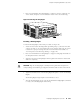
Press the power switch on two power supply faceplates to the ON position. When
the power supply has powered on successfully, the green OUTPUT OK LED lights
steadily.
NOTE: After powering off a power supply, wait at least 60 seconds before turning it
back on. After powering on a power supply, wait at least 60 seconds before turning
it off.
If the router is completely powered off when you power on the power supply, the
Routing Engine boots as the power supply completes its startup sequence. If the
Routing Engine finishes booting and you need to power off the router again, first
issue the CLI request system halt command. For more information, see “Disconnecting
AC Power from the Router” on page 111 or “Disconnecting DC Power from the
Router” on page 117.
After a power supply is powered on, it can take up to 60 seconds for status
indicators—such as LEDs on the power supply and show chassis commands—to
indicate that the power supply is functioning normally. Ignore error indicators that
appear during the first 60 seconds.
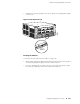
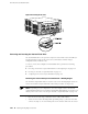
13.
Press the power switch for the remaining power supplies to the ON ( | ) position
and observe the LEDs on each power supply faceplate. They should light as
described in the previous step.
Replacing Power System Components ■ 119
Chapter 13: Replacing Hardware Components