
Network Router User Manual

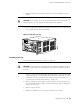

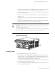
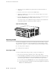


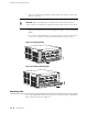

Table 18: Tools and Parts Required (continued)
ComponentsTool or part
Serial cable to AUX/MODEM or CONSOLE Routing Engine
port
Flat-blade (–) screwdriver, 2.5 mm
Internal flash driveNeedlenose pliers
■
Fan tray
■
CFEB
■
DC power cables
■
PIC
■
Power supply (AC or DC)
■
Routing Engine
Phillips (+) screwdrivers, numbers
1 and 2
Fiber-optic PIC or PIC cableRubber safety cap
Replacing a Fan Tray
The fan trays install into the rear of the chassis, as shown in Figure 2. They each
house eight fans and weigh approximately 4 lb (1.8 kg). To replace a fan tray, perform
the following procedures:
■ Removing a Fan Tray on page 88
■ Installing a Fan Tray on page 89
Removing a Fan Tray
To remove a fan tray, follow this procedure (see Figure 27):
CAUTION: Do not remove both fan trays for more than one minute while the router
is operating. The fans are the sole source of cooling, and the router can overheat
when they are absent.
1. Attach an electrostatic discharge (ESD) grounding strap to your bare wrist and
connect the strap to one of the ESD points on the chassis. Make sure the router
is attached to a proper earth ground. For more information about ESD, see
“Preventing Electrostatic Discharge Damage” on page 140.
2. Loosen the thumbscrew at the top of the fan tray faceplate, using a Phillips
screwdriver if necessary.
88 ■ Replacing a Fan Tray
M10i Internet Router Hardware Guide