
Services Routers Hardware Guide


For information about the AC power supply, see “J2320 Power System” on page 18,
“J2350 Power System” on page 18, “J4350 Power System” on page 30 or “J6350
Power System” on page 31.
To connect the power cord during initial installation, see “Connecting
Power” on page 84.
To replace the AC power cord, see “Replacing AC Power Supply Cords” on page 139.
DC Power, Connection, and Power Cable Specifications
Each DC power supply has a single DC input (–48 VDC and return) that requires a
dedicated circuit breaker:
■ J2350 routers—minimum 15 A (–48 VDC)
■ J4350 and J6350 routers—minimum 25 A (–48 VDC)
If the J6350 router contains redundant DC power supplies, one power supply must
be powered by a dedicated power feed derived from feed A, and the other power
supply must be powered by a dedicated power feed derived from feed B. This
configuration provides the commonly deployed A/B feed redundancy for the system.
Most sites distribute DC power through a main conduit that leads to frame-mounted
DC power distribution panels, one of which might be located at the top of the rack
that houses the router. A pair of cables (one input and one return) connects each set
of terminal studs to the power distribution panel.
CAUTION: You must ensure that power connections maintain the proper polarity.
The power source cables might be labeled (+) and (–) to indicate their polarity. There
is no standard color coding for DC power cables. The color coding used by the external
DC power source at your site determines the color coding for the leads on the power
cables that attach to the terminal studs on each power supply.
WARNING: Power plant ground and chassis ground must be connected to the same
building ground.
CAUTION: Before router installation begins, a licensed electrician must attach a cable
lug to the grounding and power cables that you supply. A cable with an incorrectly
attached lug can damage the router.
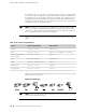
Each DC power cable (–48 VDC and return) must be 14 AWG single-strand wire cable,
or as permitted by the local code. Each lug attached to the power cables must be a
ring-type, vinyl-insulated TV14-6R lug, or equivalent.
Power Guidelines, Requirements, and Specifications ■ 71
Chapter 4: Preparing for Router Installation