
Switch User Manual


The tables in this section list the N+1 power requirements of different EX8200 switch
configurations:
•
Table 26 on page 50—Lists the N+1 power requirements of EX8208 switch
configurations that use 2000 W DC power supplies.
•
Table 27 on page 50—Lists the N+1 powerrequirements of EX8216 switch configurations
that use 3000 W DC power supplies.
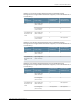
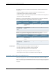
Table 26: N+1 Power Redundancy Configurations for Different EX8208
Switch Configurations Using 2000 W DC Power Supplies
Power Supplies
Needed for N+1
Power Supplies
Needed (N)Input Voltage
Switch
Configuration
21–40 VDC through
–72 VDC
Base
43–40 VDC through
–72 VDC
Fully loaded with
8-port SFP+ line
cards
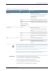
Table 27: N+1 Power Redundancy Configurations for Different EX8216
Switch Configurations Using 3000 W DC Power Supplies
Power Supplies
Needed for N+1
Power Supplies
Needed (N)Input Voltage
Switch
Configuration
21–40 VDC through
–72 VDC
Base
54–40 VDC through
–72 VDC
Fully loaded with
8-port SFP+ line
cards
Related Topics DC Power Specifications for EX8200 Switches on page 110•
• DC Power Supply LEDs in an EX8200 Switch on page 50
• Calculating Power Requirements for an EX8216 Switch
• Installing a DC Power Supply in an EX8200 Switch on page 152
• Removing a DC Power Supply from an EX8200 Switch on page 209
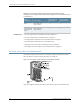
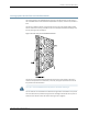
DC Power Supply LEDs in an EX8200 Switch
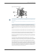
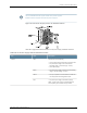
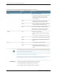
A DC power supply has four LEDs on its faceplate: FAIL, OUT OK, A IN OK, and B IN OK
LEDs. The text A or B next to the OK IN LEDs indicates which input lug the LED corresponds
to. All four LEDs display information about the status of the power supply. See Figure 29
on page 51.
Copyright © 2010, Juniper Networks, Inc.50
Complete Hardware Guide for EX8208 Ethernet Switches