
- Juniper Networks, Inc. User's Guide power supply NETSCREEN-5000 SERIES


NetScreen-5000 Series 47
M
ODULE
LED D
ESCRIPTIONS
This section provides descriptions of the LEDs on NetScreen-5000 Series modules. Two
types of LEDs exist on the modules:
• Status LEDs. These LEDs reflect certain conditions that exist on the system at
large and do not explicitly refer to a given port.
• Port LEDs. These LEDs reflect basic conditions (for example, a link connection
status) that exist for a specific port.
S
TATUS
LED S
TATES
This section describes Status LED states on all modules.
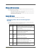
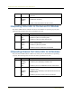
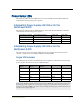
Interpreting Status LEDs for the Management
Modules
The Status LEDs indicate whether the management module is operating properly. The
following table describes the status possibilities for each.
LED LED Color Meaning of the LED
CPU
Utilization
green Consists of an array of five LEDs that indicate the current level of
CPU utilization. Utilization is defined as the amount of traffic
detected on the device at any given time. The CPU utilization LEDs
represent the following percentages of possible utilization: 5%, 10%,
25%, 50%, and 90%.
off When all are off, indicates less than 5 percent CPU use.
POWER green Indicates the system is receiving power.
off Indicates the system is not receiving power.
red Indicates the power has a problem.
STATUS blinking
green
Indicates the system is operational.
blinking
amber
Indicates the system is booting up.
off Indicates the module is not operational.
HA green Indicates the module is a master in a redundancy cluster.
red Indicates the module is ineligible to be a backup.
amber Indicates the module is a backup in a redundancy cluster.
off Indicates that no HA activity has been defined.
ALARM red Indicates an alarm which could mean a system failure.
blinking red Indicates a self-test failure during the bootup process.