
Instruction Manual
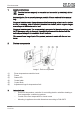
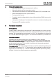
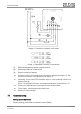
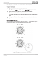
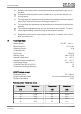
Table Of Contents

Image2: Connection example of the insert
Image3: Clampable conductor cross-section
(7) External temperature sensor (remote sensor)
(8) Switching contact of central clock
(9) Electric underfloor heating
■ Connect insert (1) according to the connection diagram (see figure 2). Ob-
serve the conductor cross-sections (see figure 3).
■ Optionally, connect the ECO operation input Ø via a switching contact of a
central clock (8).
If 230 V is applied to the input, the target temperature is reduced by 4 °C.
■ Fit device in appliance box; terminals must be at the bottom.
■ Fit the frame, central plate and control knob.
■ Switch on mains voltage.
7.1 Commissioning
Setting control behaviour
Factory setting: pulse width modulated control (PWM)
Floor thermostat
7 / 10
82404923 29.11.2022
J0082404923