
Datasheet

V3.00/EN/00542385
Data Sheet 701155 Page 9/19
70115500T10Z000K000
-802*PE+&R.*
'HOLYHU\DGGUHVV 0DFNHQURGWVWUDH
)XOGD*HUPDQ\
3RVWDODGGUHVV
)XOGD*HUPDQ\
3KRQH
)D[
(PDLO PDLO#MXPRQHW
,QWHUQHW ZZZMXPRQHW
-802,QVWUXPHQW&R/WG
-802+RXVH
7HPSOH%DQN5LYHUZD\
+DUORZ(VVH[&0'<8.
3KRQH
)D[
(PDLO VDOHV#MXPRFRXN
,QWHUQHW ZZZMXPRFRXN
-8023URFHVV&RQWURO,QF
0\HUV5RDG
(DVW6\UDFXVH1<86$
3KRQH
)D[
(PDLO LQIRXV#MXPRQHW
,QWHUQHW ZZZMXPRXVDFRP
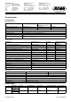
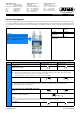
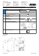
Dimensions
Type 701155/...
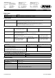
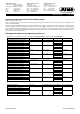
(4) to to 20 mA for both analog inputs
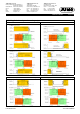
Caution:
When only one probe (SIL2) is connected, the temperature limiter device is reduced from SIL3 to SIL2! However, the internal 2-channel structure
(1oo2D) in the device still remains. Both channels measure the same current signal due to the simplified external wiring.
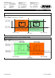
4 Digital input
Connection to a potential-free contact
5 Analog output:
0to 20mA
4 to 20 mA (default setting)
0(2) ... 10 V
9 Voltage supply
According to nameplate
AC:
L1 line conductor
N neutral conductor
DC:
(L+)
(L-)
10 Alarm relay output (zero-current state)
Relay (changeover contact) with fuse cut-out
11 Pre-alarm relay output (KV)
Relay (changeover contact)
Legend Comment Screw terminals Screw terminals
2
+
–
I
x
7
4
5
Ground
9
10
+
–
I
x,
U
x
L1N
L1N
L+L-
L+L-
Internal
circuitry
S
P
11
12 13
Ö