
Datasheet


V3.00/EN/00542385
Data Sheet 701155 Page 8/19
70115500T10Z000K000
-802*PE+&R.*
'HOLYHU\DGGUHVV 0DFNHQURGWVWUDH
)XOGD*HUPDQ\
3RVWDODGGUHVV
)XOGD*HUPDQ\
3KRQH
)D[
(PDLO PDLO#MXPRQHW
,QWHUQHW ZZZMXPRQHW
-802,QVWUXPHQW&R/WG
-802+RXVH
7HPSOH%DQN5LYHUZD\
+DUORZ(VVH[&0'<8.
3KRQH
)D[
(PDLO VDOHV#MXPRFRXN
,QWHUQHW ZZZMXPRFRXN
-8023URFHVV&RQWURO,QF
0\HUV5RDG
(DVW6\UDFXVH1<86$
3KRQH
)D[
(PDLO LQIRXV#MXPRQHW
,QWHUQHW ZZZMXPRXVDFRP
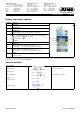
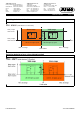
Connection diagram
The connection diagram in the data sheet provides preliminary information about the connection options. For the electrical connection,
only use the installation instructions or the operating manual. The knowledge and the correct technical execution of the safety informa-
tion and warnings contained in these documents are mandatory for installation, electrical connection, startup, and for safety during op-
eration.
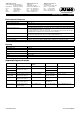
The connection is made via screw terminals. Wire Admissible cross
section
One-wire ≤ 2.5 mm
2
Fine-strand,
with ferrule
≤ 1.5 mm
2
Tightening torque of the screws:
max. 0.5 Nm
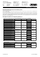
Legend Comment Screw terminals Screw terminals
1, 2
Analog input 1 (E1) Analog input 2 (E2)
Thermocouple /
Double thermocouple
RTD temperature probe in two-wire circuit
RTD temperature probe Pt100/Pt1000 in three-wire
circuit
RTD temperature probe Pt100 in two-wire circuit, sin-
gle sensor for both analog inputs
Caution:
When only one probe (SIL2) is connected, the temperature limiter device is reduced from SIL3 to SIL2! However, the internal 2-channel structure
(1oo2D) in the device still remains. Both channels measure the same sensor due to the simplified external wiring.
(4) to 20 mA
1
2
4
5
9
10
11
+
–
2
3
+
–
7
8
V
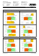
When connecting double thermocouples, the measuring circuits (E1) and (E2) must be isolated. That means that both
thermocouples have no electrical connection to the protection fitting
and furthermore no electrical connection to each other (isolated assembly).
J
13
J
68
A
Enter the line resistance for RTD temperature probes in two-wire circuit when using greater line lengths.
Setup program: edit => analog inputs
123
J
678
J
J
13 68
2
3
+
–
I
x
7
8
+
–
I
x
Caution:
The cover cap must be removed prior to
wiring and put back on when finished.
This is necessary for the proper opera-
tion of the probes in the Ex-area!