
Datasheet


Page 12/19
Data Sheet 701155
V3.00/EN/00542385
70115500T10Z000K000
-802*PE+&R.*
'HOLYHU\DGGUHVV 0DFNHQURGWVWUDH
)XOGD*HUPDQ\
3RVWDODGGUHVV
)XOGD*HUPDQ\
3KRQH
)D[
(PDLO PDLO#MXPRQHW
,QWHUQHW ZZZMXPRQHW
-802,QVWUXPHQW&R/WG
-802+RXVH
7HPSOH%DQN5LYHUZD\
+DUORZ(VVH[&0'<8.
3KRQH
)D[
(PDLO VDOHV#MXPRFRXN
,QWHUQHW ZZZMXPRFRXN
-8023URFHVV&RQWURO,QF
0\HUV5RDG
(DVW6\UDFXVH1<86$
3KRQH
)D[
(PDLO LQIRXV#MXPRQHW
,QWHUQHW ZZZMXPRXVDFRP
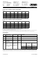
Protective, regulation, and control devices
Safety temperature monitor STW
1
The safety temperature monitor is a device that is automatically reset after responding if the sensor temperature has fallen below or ris-
en above the set limit value by an amount equal to the switching differential. Possible settings: monitoring for limit value overrange or
underrange.
Mode of operations:
Minimum requirements: 2B, 2K, 2P
Additional requirements fulfilled: 2N, 2D
Safety temperature limiter STB
1
The safety temperature limiter is a device that is permanently locked after responding.
Manual reset using the RESET key is possible once the probe temperature has fallen below / has exceeded the limit value by the
amount of the switching differential. Possible settings: monitoring for overrange or underrange.
Mode of operations:
Minimum requirements: 2B, 2J, 2V, 2K, 2P and adjustable with special tools
Additional requirements fulfilled: 2N, 2F, 2D
1.
For more detailed explanation, see DIN EN 14 597.
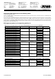
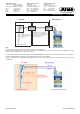
Connection possibilities of the sensors
The JUMO safetyM STB/STW evaluation device structure is basically identical. Various possibilities are available for sensor connection.
These possibilities are listed in the following table along with the achievable SIL level:
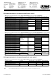
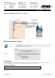
Note:
Variants 1 to 4 were evaluated with JUMO probes according to data sheets 901006 and 902006. For variant 5 no sensor technology was included.
In this case, the plant operator selects the sensor technology. For this reason, the plant operator is responsible for evaluating the achievable SIL.
If the used SIL-capable sensor consists of hardware and software (e.g. transmitter), the maximum SIL that can be achieved – irrespective of the
architecture – is the one according to which the sensor software was developed (so, for example, if the sensor software has SIL 2, the max.
achievable SIL is 2).
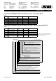
The possibility to connect passive sensors such as double thermocouples or Pt100/Pt1000 sensors means that the sensors do not necessarily
require a SIL qualification. In this case, the specification of the failure rates for the passive sensors is sufficient for the SIL qualification of the
overall system. The plant operator must always determine the PFD
avg
and/or PFH value of the overall safety chain to determine the achieved SIL.
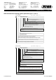
Variant Connected sensors
Architecture Achievable SIL
Sensor technology Logic
1 1 × Pt100 two-wire circuit,
single sensor
1oo1 1oo2D 2
1a 2x Pt100/1000 two-wire cir-
cuit
1oo2 1oo2D 3
2 2x Pt100/1000 three-wire cir-
cuit
1oo2 1oo2D 3
3 2x thermocouple 1oo2 1oo2D 3
4 1x Pt100/1000
two-wire and three-wire circuit
1x thermocouple
1oo2 1oo2D 3
5 STB/STW 70.1150 without
1oo2D sensor technology ar-
chitecture:
No probe or use of 4 to 20 mA
(means that the sensor is not
taken into account for calcula-
tion).
Sensors connected
by the plant opera-
tor: architecture ac-
cording to connec-
tion 1oo1 or 1oo2
1oo2D SIL (architecture) of
the sensor used
(HW only)
Systematic com-
patibility (SC) of the
sensor used
Max. achievable SIL
of the system with
1oo1 sensor tech-
nology architecture
Max. achievable SIL
of the system with
1oo2 sensor technol-
ogy architecture
1111
1212
2222
2323
3333