
Operating Manual Owner's manual
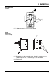
4 Installation
20
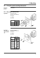
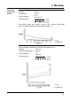
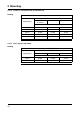
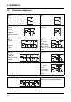
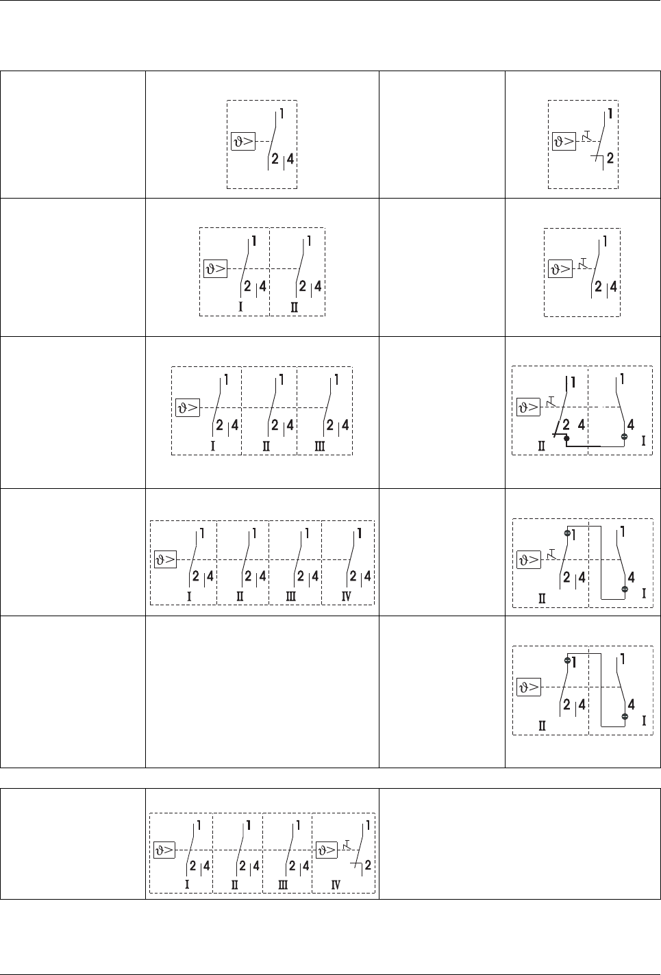
4.3 Connection diagrams
EM-1
EM-2
EM-3
EM-4
EM-5
EMF-13
EMF-23
EMF-33
Setpoint: I
Follow-on contact:
II
EM-4/574
EM-5/574
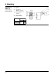
EMF-133
EMF-233
EMF-333
Setpoint: I
Follow-on contact:
II, III
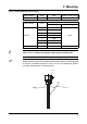
EM-40
EM-50
n.c. (break)
contact
on measuring
system failure
and T
< -10 °C: I
limit: II
EMF-1333
EMF-2333
EMF-3333
Setpoint: I
Follow-on contact:
II, III, IV
EM-40/574
EM-50/574
EM-20
EM-30
n.c. (break)
contact
on measuring
system failure
and T
< -10 °C: I
limit: II
Example: EMF-1334 For other variants, the connection
diagrams are combined appropriately.