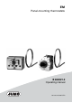
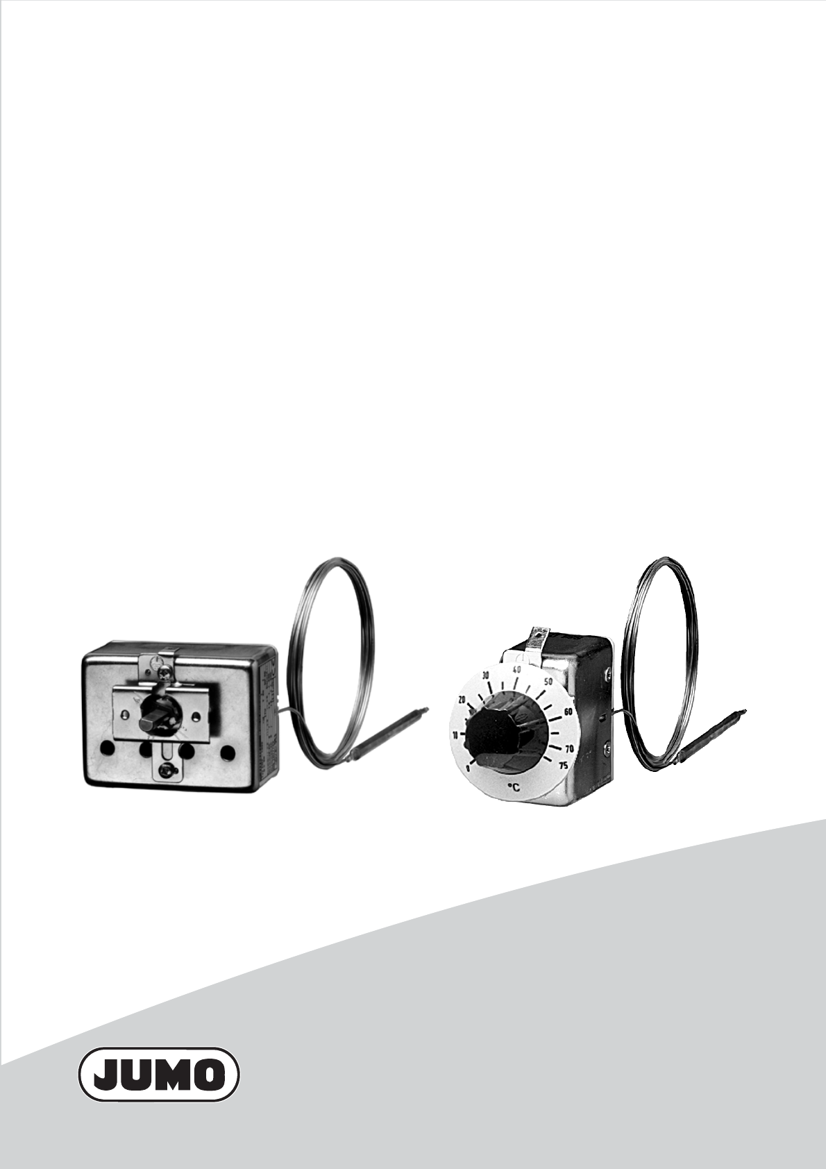
EM Panel-mounting thermostats B 602021.
Please read these Operating Instructions before commissioning the instrument. Keep the manual in a place that is accessible to all users at all times. Please assist us to improve these operating instructions, where necessary. Your comments will be appreciated. Phone+49 661 6003-0 Fax+49 661 6003-607 All necessary settings and possible adjustments inside the instrument are described in these operating instructions.
Contents 1 Introduction .................................................................................. 4 1.1 Typographical conventions ......................................................................... 4 1.1.1 Warning signs ................................................................................................. 4 1.1.2 Note signs ...................................................................................................... 4 1.2 Application ....................................
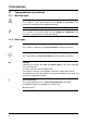
1 Introduction 1.1 Typographical conventions 1.1.1 Warning signs V Danger A 1.1.2 H v abc1 This symbol is used when there may be danger to personnel if the instructions are ignored or not followed correctly! Caution This symbol is used when there may be damage to equipment if the instructions are ignored or not followed correctly! Note signs Note This symbol is used when your special attention is drawn to a remark. Reference This symbol refers to further information in other chapters or sections.
1 Introduction 1.2 Application Thermostats control and monitor thermal processes. Panel-mounting thermostats operate on the principle of liquid or gas expansion. A microswitch serves as the electrical switching device. The devices of the EM model series can be supplied as temperature controllers TR, operating temperature limiters TW, operating temperature limiters TB, protection temperature limiters STW and protection temperature limiters STB.
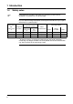
1 Introduction 1.4 Safety notes H Filling liquid may escape in the event of a measuring system fracture. At present, any health risks can be excluded. Physical and toxicological properties of the expansion fluid that may escape in the event of a system fracture. Control range with end of scale °C Dangerous reactions < +200 Fire and explosion hazard Ignition temperature °C Explosion limit % v/v no +355 0.
2 Instrument identification 2.
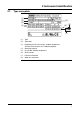
2 Instrument identification 2.2 Type designation Type designation EM - .. - .. / .. Panel-mounting thermostat with one microswitch EMF - .... - .. / .. Panel-mounting thermostat with 2, 3 or 4 microswitches Standard connection "10" (plain cylindrical probe) 8 - 1... Temperature controller TR with changeover contact - 2... Operating temperature limiter TW with changeover contact - 3...
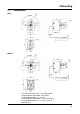
3 Mounting 3.1 Dimensions EM-1 EMF-13 ( 1 ) Faston connector A 6.3 x 0.
3 Mounting EMF-133 EMF-1333 ( 1 ) Faston connector A 6.3 x 0.
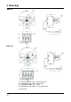
3 Mounting 3.2 Fixing the panel-mounting thermostat Operating position 3.2.1 unrestricted Mounting the switch head Type EM.-1... by two M3 screws (M4 with extra code 704) on chassis: ( 1 ) Screw ( 2 ) Panel Extra code Series 704 705 Dim. (mm) G B 3.5 22 4.5 28 3.5 33 (1) (2) (1) Type EM.-2... , -3... , -4... , -5...
3 Mounting Type EM.-4, -5, -40 or -50 central fixing (extra code 710) ( 1 ) Panel ( 2 ) Fixing nut M10 x 1 (13 a/f) (3) Cap nut M10 x 1 (10 a/f) (4) Reset button Type EM-4, -5 EM-40, -50, 12 Dim.
3 Mounting 3.3 Capillary / temperature probe / pocket 3.3.1 General A Cutting through or kinking the capillary of the panel-mounting thermostat will lead to permanent instrument failure! Minimum permissible bending radius of the capillary is 5 mm. The temperature probe must be mounted in a JUMO pocket, otherwise the approval of the panel-mounting thermostat becomes invalid. The temperature probe must be completely immersed in the medium to be measured.
3 Mounting 3.4 Permissible loading on the pocket 3.4.1 Pockets 20, 22/23, 40 and 41/42 A 3.4.1.1 The values given below refer to the maximum loading on the probe mounting concerned. The maximum pressure which can be sealed depends on the mounting conditions and may possibly be lower. Steel pockets 22, 23, 32, 41, 42 and 45 Materials Tube: St35.8 I Screw-in nipple up to 300°C: Steel 1.0038 Weld-in nipple: Steel 1.5415 Loading Tube diameter D Temperature 8 x 0.75 mm or conical 10 x 0.75 mm 15 x 0.
3 Mounting Permissible incident flow velocity Material: Temperature: Thermal medium: St35.8 I +200°C air ( 1 ) water, oil ( 2 ) Tube diameter D: .............. 08 mm 10 mm 15 mm Permissible incident flow velocity (m/sec) at the maximum permissible pressure loading and different immersion tube lengths “S”. ( 1 ) Air ( 2 ) Water, oil Permissible incident flow velocity (m/sec) at the maximum permissible pressure loading and different immersion tube temperatures “t”. Material: St35.
3 Mounting 3.4.1.2 Stainless steel pockets 20, 22, 40 and 41/42 Loading Material of tube and nipple: stainless steel (1.4571) Tube diameter D Temperature 8 x 0.75 mm or conical 10 x 0.75 mm 15 x 0.75 mm Max. permissible pressure 3.4.1.3 100°C 92 bar 74 bar 50 bar 150°C 88 bar 71 bar 48 bar 200°C 83 bar 67 bar 45 bar 300°C 72 bar 58 bar 39 bar 400°C 67 bar 54 bar 36 bar Brass pockets 20 and 40 Loading Material of tube and nipple: CuZn Tube diameter D Temperature 8 x 0.
3 Mounting 3.4.1.4 Probe mountings 50, 52 and 54 Nipple material CuZn steel stainless steel (1.4571) Temperature °C 200 300 400 Probe material Ø mm Cu-DHP St35 / 1.4571 Thermostat action TR, TW, TB 4 6 bar 5 5 bar 6 4 bar 7 3 bar 8 3 bar 9 3 bar 10 3 bar 4 - 10 10 bar STB, STW (STB) 2 bar 2 bar A Forms 10, 15, 21, 60, 65 may only be used in unpressurized media.
4 Installation 4.1 Regulations and notes ■ The electrical connection must only be carried out by qualified personnel. ■ The choice of cable, the installation and the electrical connection must conform to the requirements of VDE 0100 “Regulations on the Installation of Power Circuits with Nominal Voltages below 1000 V” or the appropriate local regulations. ■ If contact with live parts is possible while working on the instrument, it must be completely disconnected from the electrical supply.
4 Installation Plug connection (standard) (1) ( 1 ) = faston connector A 6.3 x 0.8 to DIN 46 244 Screw connection (extra code 699) 2 1 ( 1 ) Receptacle 6.3 with connection screw, suitable for conductor crosssections up to 2.
4 Installation 4.3 Connection diagrams EM-1 EM-2 EM-3 EM-4 EM-5 EMF-13 EMF-23 EMF-33 EM-4/574 EM-5/574 Setpoint: I Follow-on contact: II EMF-133 EMF-233 EMF-333 Setpoint: I Follow-on contact: II, III EMF-1333 EMF-2333 EMF-3333 EM-40 EM-50 n.c. (break) contact on measuring system failure and T < -10 °C: I limit: II EM-40/574 EM-50/574 Setpoint: I Follow-on contact: II, III, IV EM-20 EM-30 n.c.
5 Settings 5.1 Unlocking the operating temperature limiter (TB) or protection temperature limiter (STB) EM-4 EMF-4... EM-5 EMF-5... EM-40 EM-50 with fixing bracket 704, 705 After the temperature has dropped by about 10% of span below the set limit (critical temperature), the microswitch can be reset. ✱ Push the reset button using a small screwdriver EM-4 EMF-4... EM-5 EMF-5...
5 Settings 5.2 EM-1 EMF-1... Setpoint adjustment ( 1 ) Setpoint marker ( 2 ) External scale ( 3 ) Setpoint knob ( 4 ) Scale graduation ✱ Rotate the setpoint knob by hand over the external scale (1) (2) °C °C EM-2 EMF-2... EM-5 EMF-5... EM-20 EM-50 ( 1 ) Setpoint spindle ( 2 ) Scale graduation ( 3 ) Setpoint marker ✱ Rotate the setpoint spindle over the internal scale using a screwdriver (3) (4) (1) (2) (3) EM-3 EMF-3... EM-4 EMF-4... EM-30 EM-40 H 5.
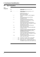
6 Instrument description 6.1 Technical data Permissible ambient temperature Capillary TR,TW Switch head TB, STW(STB) STB max. TR,TW TB, STW(STB) STB see nameplate -40 °C min. for end of scale -20 °C < 200 °C -20 °C -20 °C 0 °C ≥ 200 °C ≤ 350 °C > 350 °C ≤ 500 °C -40 °C Permissible probe temperature max.: end of scale / limit value +15%, (for end of scale between +90 °C and 120 °C = min. 25 °C Permissible storage temperature max. +50 °C, min.
6 Instrument description Contact rating Type EM-... 1, 2, 3, 20, 30 4, 5, 40, 50 1, 2, 3, 20, 30 Switching differential % 2.5 / 5 /7 / 10 -2.5 / 5 / 6 / 7 / 10 1, 2, 3, 20, 30 Current Terminal 2 Terminal 4 2A 10 A 16(3) 8(1.5) A 0.25 A 0.25 A 6(2) 1/3 16(3) A 4/574, 5/574, 40/574, 50/574 -- -- 400 V AC +10% -- 0.25 A 4, 5, 40, 50 Voltage 0.25 A 0.1 A extra code “702” -- 16(3) A 2(1) A 230 V AC +10% p.f. = 1 (0.6) 230 V DC +10% 230 V AC +10% p.f. = 1 (0.6) 230 V DC +10% 230 V AC +10% p.
6 Instrument description Switching point accuracy (in % of scale span; referred to setpoint or limit value at TA +22 °C, with rising temperature) Switching differential in % Type EM-... liquid-filled gas-filled 1 / 2.5 5 7 1 / 2.5 5 7 -- -3/5 6 / 10 -3/5 6 / 10 -- 7 10 -- -- 1 2, 3 4, 4/574, 5, 5/574 20, 30 40, 40/574, 50, 50/574 Protection EN 60 529 - IP00 Pollution degree 2 Operating medium water, oil, air, superheated steam Time constant t0.
6 Instrument description Nominal position unrestricted Weight approx. 0.2 kg Capillary and probe material End of scale Capillary Probe up to +200 °C copper, Mat. Ref. Cu-DHP 1.5 mm diameter copper, Mat. Ref. Cu-DHP brazed up to +350 °C copper, Mat. Ref. Cu-DHP 1.5 mm diameter stainless steel, Mat. Ref. 1.4571 brazed up to +500 °C stainless steel, 1.5 mm diameter stainless steel, Mat. Ref. 1.4571 welded at extra cost up to +350 °C Minimum bending radius of capillary stainless steel, 1.
JUMO GmbH & Co. KG JUMO Instrument Co. Ltd. JUMO Process Control, Inc. Street address: Moritz-Juchheim-Straße 1 36039 Fulda, Germany Delivery address: Mackenrodtstraße 14 36039 Fulda, Germany Postal address: 36035 Fulda, Germany Phone: +49 661 6003-0 Fax: +49 661 6003-607 E-mail: mail@jumo.net Internet: www.jumo.net JUMO House Temple Bank, Riverway Harlow - Essex CM20 2DY, UK Phone: +44 1279 63 55 33 Fax: +44 1279 63 52 62 E-mail: sales@jumo.co.uk Internet: www.jumo.co.