
Operating Manual

4 Installation
16
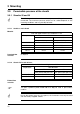
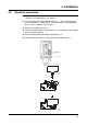
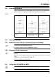
Connection
diagrams
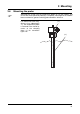
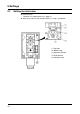
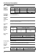
4.2.1 Closing the case
✱ Make sure that the plastic gasket in the lower part of the case ( 2 ) is seated
correctly.
✱ Place the upper part of the case ( 1 ) onto the lower part ( 2 ).
✱ Tighten the lead-sealable cheese-head screws ( 5 ).
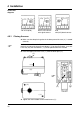
TW / STW (STB) STB as N/C contact
with signal contact
STB
with (N/C) break contact
H
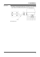
On thermostats with code -70, the external reset button ( 3 ) must be located
precisely on top of the internal reset button ( 4 ) for the microswitch, since this
is the only way the reset button ( 3 ) can be operated from the outside.
H
( 1 )
( 2 )
( 3 )
( 4 )
( 5 )
( 5 )