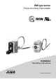
EM type series Panel-mounting thermostats B 602026.
Please read this operating manual before starting up the device. Keep the operating manual in a place accessible to all users at all times. Please help us to improve these instructions where necessary. Your comments are highly appreciated. Phone +49(0)6 61 - 60 03-7 16 Fax +49(0)6 61 - 60 03-5 04 All necessary settings and required work inside the device are described in this operating manual.
Inhalt 1 Introduction .................................................................................. 4 1.1 Typographical conventions ......................................................................... 4 1.1.1 Warning signs ................................................................................................. 4 1.1.2 Indicative signs ............................................................................................... 4 1.2 Application .......................................
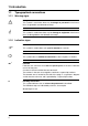
1 Introduction 1.1 Typographical conventions 1.1.1 Warning signs V Danger A 1.1.2 H v abc1 This symbol is used when there may be danger to personnel if the instructions are ignored or not followed correctly! Caution This symbol is used where there may be damage to equipment if the instructions are disregarded or not followed accurately! Indicative signs Note This symbol is used to draw your special attention to a remark.
1 Introduction 1.2 Application Thermostats are used to control and monitor thermal processes. Panel-mounting thermostats operate according to the fluid or gas expansion principle. The electrical switching element is a micro switch. The devices of the EM type series are available as safety -temperature monitors STW and safety temperature limiters STB. In the event of a malfunction, the STB switches the monitored machine line to an operational safe status.
1 Introduction 1.4 Safety information H Filling fluid can emerge in the event of a measuring system break. A hazard to health is excluded as per the present information. Physical and toxic features of the expansion means, which could emerge in the event of a measuring system break: Control range with scale limit value °C Hazardous reaction < +200 Fire and explosion hazard Ignition temperature °C Explosion limit Vol.% no +355 0.
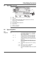
2 Identifying the device 2.1 Type plate (example) (1) (2) (3) (5) (7) (4) (6) (8) ( 1 ) Type ( 2 ) Type code ( 3 ) Control- and limit value range / ambient temperature at which this thermostat was calibrated (option) ( 4 ) Contact rating ( 5 ) Permissible ambient temperature ( 6 ) Serial number ( 7 ) Week of manufacture ( 8 ) Year of manufacture 2.2 Type designation Type designation EM - .. - .. - .. / ..
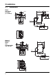
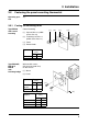
3 Installation 3.1 Dimensions EM-80 with central fastening (as standard) 12 46 SW10 SW13 16 21 26 6 15.5 Ø 1.5 Ød 36.5 29 L 52 1 2 6 46 G 21 16 21 EM-20-E EM-30-E EM-80 with fastening bridge 704, 705, 706 B 36.5 38 Ød Ø 1.5 L 52 1 8 2.
3 Installation 3.2 Fastening the panel-mounting thermostat Operating position 3.2.
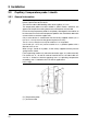
3 Installation 3.3 Capillary / temperature probe / sheath 3.3.1 General information A Bending/kinking or cutting the capillary of the panel-mounting thermostats will lead to a permanent device failure! The minimum admissible bending radius of the capillary is 5 mm. The temperature probe must be installed in JUMO sheaths, otherwise, the approval of the panel-mounting thermostats will become null and void. Ensure that the temperature probe is completely submerged in the medium to be measured.
3 Installation 3.3.2 Approved process connections Temperature probe 10 Screwconnections 50, 52, 54, 60, 65 Sheaths 20, 21, 22, 23, 24, 40, 41, 42 H refer to data sheet 606710 ! 3.3.3 Sheath made of steel 22, 23, 32, 41, 42 and 45 Material Tube St 35.8 I Screw-in nipples Steel 1.0038 Welding nipples Steel 1.5415 Capacity Temperature 100 °C 150 °C 200 °C 300 °C 350 °C max. admissible operating temperature Pipe diameter 8 x 0.75 mm or 10 x 0.75 mm 15 x 0.
3 Installation permissible flow rates Material: Temperature: Heat transfer oil: St35.8 I +200 °C Air ( 1 ) water, oil ( 2 ) Pipe diameter Ø: .............. 08 mm 10 mm 15 mm Permissible flow rate [m/s] at maximum admissible pressure load and different immersion tube length "S“ ( 1 ) Air ( 2 ) Water, oil Immersion tube length [mm] Permissible flow rate [m/s] at maximum admissible pressure load and different immersion tube temperature. Material: St35.
3 Installation 3.3.4 Sheath made of stainless steel 20, 22, 40 and 41 Capacity Material of pipe and nipple: Stainless steel (1.4571) Pipe diameter Ø Temperature 8 x 0.75 mm or conical 10 x 0.75 mm 15 x 0.75 mm Maximum admissible pressure 3.3.
3 Installation A Design 10, 15, 21, 60, 65: only use in pressureless medium. H Ensure that the temperature probe (2) is completely submerged in the medium because otherwise, greater switching point deviations will occur. For connection types 20, 21 and 22, the temperature probe is fixed in the sheath with the clamping piece ( 1 ).
4 Installation 4.1 Standards and information ■ Only allow electricians to carry out the electrical connection. ■ The choice of cable, the installation and the electrical connection of the device must conform to the requirements of VDE 0100 "Regulations on the Installation of Power Circuits with Nominal Voltages below 1000 V" and/or the appropriate local regulations. ■ If contact with live parts is possible while working on the device, it must be completely isolated from the supply.
4 Installation Plug-in connector (as standard) (1) ( 1 ) = Tab connector DIN 46 244-A 6.3 x 0.8 Screwconnection (extra code 699) 2 1 ( 1 ) Plug-in sleeve 6.3 with connection screw suitable for wires up to 2.5 mm2; fitting type "699", without auxiliary means ( 2 ) Terminal strip 4.
5 Settings 5.1 Unlocking the safety temperature limiter (STB) EM-80, with fastening bridge 704, 705, 706 Once the set limit value is gone below (dangerous temperature) by approx. 10% of the scale range, the micro switch can be unlocked. ✱ Actuate the restart knob using a small screwdriver.
°C 5 Settings 5.2 EM-20-E Limit value setting ( 1 ) Set point value setter ( 2 ) Scale subdivision ( 3 ) Set point value indicator (1) ✱ Adjust the set point value setter via the internal scale using a screwdriver (2) (3) EM-30-E EM-80 5.3 H The limit value is permanently factory set and sealed. Readjustment is not admissible. Self-monitoring of the STB and STW (STB) If the measuring system is destroyed, i.e.
6 Device Description 6.1 Technical data Permissible ambient temperature Capillary Switch head STW (STB) STW (STB) STW (STB) STW (STB) STB STB extra code extra code STB STB 707 707 max. see nameplate -40 °C min. with scale limit value / limit value -20 °C -20 °C -40 °C < 200 °C +18 °C 0 °C ≥ 200 °C ≤ 350 °C > 350 °C ≤ 500 °C Permissible probe temperature max.: Scale limit value / limit value +15%, (with scale limit value between +90 °C and 120 °C = min.
6 Device Description maximum contact rating Current Terminal 2 Terminal 4 Type EM-20-E EM-30-E 10(2) A 2(0.4) A 0.25 A 0.25 A 10(2) A EM-80 0.25 A 0.1 A (extra code "702") -- 10(2) A 2(0.4) A 0.25 A 0.25 A EM-80/574 Voltage AC 230 V +10% cos ϕ = 1 (0.6) DC 230 V +10% AC 230 V +10% cos ϕ = 1 (0.6) DC 230 V +10% AC / DC 24 V AC 230 V +10% cos ϕ = 1 (0.
6 Device Description Protection class EN 60 529 - IP 00 Degree of soiling 2 Operating medium Water, oil, air, hot steam Time constant t0.632 Function in water in oil in air / hot steam ≤ 45 s ≤ 60 s ≤ 120 s as per EN 60 730-1 and DIN EN 60 730-2-9 and DIN EN 14597 STW(STB): 2 BKLNP STB 2 BFHKLNPV Rated position any Weight approx. 0.2 kg Material of capillary and probe Scale limit value Capillary Sensors up to +200 °C Copper mat.No.: Cu-DHP Ø 1.5 mm Copper, mat.No.
6 Device Description Average ambient temperature influence (in % from the scale range) referring to the limit value. When the ambient temperature on the switch head and / or the capillary deviates from the calibration ambient temperature +22 °C, a switching point offset occurs.
JUMO GmbH & Co. KG JUMO Instrument Co. Ltd. JUMO Process Control, Inc. Street address: Moritz-Juchheim-Straße 1 36039 Fulda, Germany Delivery address: Mackenrodtstraße 14 36039 Fulda, Germany Postal address: 36035 Fulda, Germany Phone: +49 661 6003-0 Fax: +49 661 6003-607 E-mail: mail@jumo.net Internet: www.jumo.net JUMO House Temple Bank, Riverway Harlow - Essex CM20 2DY, UK Phone: +44 1279 63 55 33 Fax: +44 1279 63 52 62 E-mail: sales@jumo.co.uk Internet: www.jumo.co.