
User Manual

2013-03-06/00073209
Data Sheet 602026 Page 3/7
JUMO GmbH & Co. KG
Delivery address: Mackenrodtstraße 14
36039 Fulda, Germany
Postal address:
36035 Fulda, Germany
Phone: +49 661 6003-0
Fax: +49 661 6003-607
E-mail: mail@jumo.net
Internet: www.jumo.net
JUMO Instrument Co. Ltd.
JUMO House
Temple Bank, Riverway
Harlow, Essex CM20 2DY, UK
Phone: +44 1279 635533
Fax: +44 1279 635262
E-mail: sales@jumo.co.uk
Internet: www.jumo.co.uk
JUMO Process Control, Inc.
6733 Myers Road
East Syracuse, NY 13057, USA
Phone: 315-437-5866
1-800-554-5866
Fax: 315-437-5860
E-mail: info.us@jumo.net
Internet: www.jumousa.com
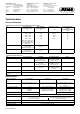
Electrical connection Standard Tab connector A 6.3 x 0.8 DIN 46244
Extra code 699 Screw connection up to 2.5 mm
2
conductor cross section (available at
extra cost) — also suitable for retrofitting —
Switching differential in %
from the limit value range
Switching function Rated value Possible actual value
STW (STB) 7 7-8
Mid ambient temperature
influence
(In % from the scale range) referring to the limit value.
Deviation of the ambient temperature at the switching head and/or capillary from the +22 °C calibration ambi-
ent temperature produces a switching head offset.
Higher ambient temperature = lower switching point
Lower ambient temperature = higher switching point
For temperatures with scale limit value / limit value
< +200 °C ≥ +200 °C ≤ +350 °C
STW (STB) Switching differential in %
77
Ambient temperature influence on the switching head in %/°C
0.43 0.35
Ambient temperature influence on the capillary in %/m
0.09 · °C · m 0.07 · °C · m
STB Ambient temperature influence on the switching head: 0.35 °C/°C
Ambient temperature influence on the capillary in °C/m 0.07 °C/°C·m
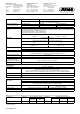
Temperature compensation Extra code "707"
For detailed information please refer to the graphical diagram on page 5.
Allowable storage tempera-
ture
-50 to +50 °C
Allowable ambient tempera-
ture when in use on the
switching head and capillary
Max. +80 °C
Min. +18 °C (0 °C for extra code "707")
Rated position (NL)
Any
Switching head
Case material Sheet steel, galvanized
Mounting Extra code 704 with 2 M4 screws, spaced 28 mm
Extra code 705 with 2 M3 screws, spaced 33 mm
Extra code 706 with 2 M3 screws, spaced 22 mm (standard for EM-20-E and EM-30-E)
Extra code 710, central mounting M10 x 1 with acorn nut (only for STB, standard for EM-80)
Protection type EN 60 529-IP 00
Weight Approx. 0.3 kg
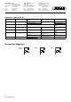
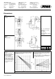
Process connection
a
a
For different process connections and thermowells refer to data sheet 606710.
EM series
with capillary
Plain cylindrical probe "10" (standard)
Screw-in thermowell "20" (upon request)
Screw-in sleeve with screw-in spigot G 1/2 form A according to DIN 3852/2
and clamping piece with fixing screw for securing the probe
Material Thermowell Up to +150 °C CuZn as a standard
Over +150 °C CrNi
Insertion length S Standard lengths: 100, 120, 150, 200, or 300 mm (different lengths upon request)
Immersion tube Ø D = 8 mm
Note: Physical and toxicological properties of the expansion medium that may escape in the event of a measuring system facture.
Control range
with scale limit value
Hazardous
reactions
Fire and explosion hazard Hazardous to
water
Information about toxicology
Ignition
temperature
Explosion
limit
Irritant Health risks Toxic
≤ +200 °C No +355 °C 0.6 - 8 V % Yes Yes
a
a
At present, no statement concerning health hazards in the event of short-term and low concentration exposure (e.g. measuring system rupture) has been made by
the health authority.
No