
Datasheet


JUMO GmbH & Co. KG
Delivery address: Mackenrodtstraße 14
36039 Fulda, Germany
Postal address:
36035 Fulda, Germany
Phone: +49 661 6003-0
Fax: +49 661 6003-607
Email: mail@jumo.net
Internet: www.jumo.net
JUMO Instrument Co. Ltd.
JUMO House
Temple Bank, Riverway
Harlow, Essex CM 20 2DY, UK
Phone: +44 1279 63 55 33
Fax: +44 1279 62 50 29
Email: sales@jumo.co.uk
Internet: www.jumo.co.uk
JUMO Process Control, Inc.
6733 Myers Road
East Syracuse, NY 13057, USA
Phone: +1 315 437 5866
Fax: +1 315 437 5860
Email: info.us@jumo.net
Internet: www.jumousa.com
V2.00/EN/00541512
Page 5/18Data Sheet 202552
20255200T10Z002K000
Setup PC program
(accessory)
The setup PC program is available in German,
English and French for configuring the
instrument. You can use it to create and edit
sets of data and transfer them to the
instrument, as well as read them out from it.
The data can be stored and printed.
Setup interface
The setup interface is integrated into the
JUMO dTRANS CR 02 by default. You can
use it, together with the setup program
(accessory) and a setup interface (accessory),
to configure the instrument.
RS232/RS485 interface
The serial interface is used for communication
with higher-level systems when the Modbus/
Jbus protocol is used.
PROFIBUS-DP
The JUMO dTRANS CR 02 can be integrated
into a fieldbus system according to the
PROFIBUS-DP standard via the PROFIBUS-
DP interface. This PROFIBUS-DP version is
especially designed for communication
between automation systems and distributed
peripheral devices at the field level and is
optimized for speed.
Data is transferred serially based on the
RS485 standard.
Using the project design tool that is included
in the delivery (GSD generator; GSD = device
master file), a standardized GSD file is created
by selecting characteristic device features of
the JUMO dTRANS CR 02. This file is used to
integrate the controller into the fieldbus
system.
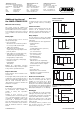
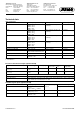
Pulse contact
Triggering condition shorter than pulse duration
Pulse width controller
(output active with x > w and P control structure)
If actual value x exceeds setpoint w, the P controller will control in proportion to the control
deviation. When the proportional range is exceeded, the controller operates with an output level
of 100 % (100 % clock ratio).
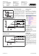
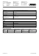
Pulse frequency controller
(output active with x > w and P control structure)
If actual value x exceeds setpoint w, the P controller will control in proportion to the control
deviation. When the proportional range is exceeded, the controller operates with an output level
of 100 % (maximum switching frequency).
Time
On
Off
Pulse duration
Pulse
contact
Time
On
Off
Trigger
condition
Process value X
Setpoint W
Proportional band X
P
100%
50%
0%
Output level y
Switching period
10%
90%
90%
10%
t
On
50%
50%
t
Off
10%
90%
X
P
X - W
0
1
100%
50%
0%
No pulses
50% of pulse frequency
Maximum pulse frequency
Setpoint W
Proportional band X
P
X
P
X - W
0
1
Output level y
Process value X
Math and logic module
The math module makes it possible to
integrate measurement value of the analog
inputs into a mathematical formula so that the
calculated process variable can be displayed.
The logic module can be used, for example, to
link binary inputs and limit comparators with
each other logically.
Up to two math or logic formulas can be
entered with the optional setup program and
the results of calculations can be displayed or
exported via outputs (via PC setup software
only).