
Datasheet


JUMO GmbH & Co. KG
Delivery address: Mackenrodtstraße 14
36039 Fulda, Germany
Postal address:
36035 Fulda, Germany
Phone: +49 661 6003-0
Fax: +49 661 6003-607
Email: mail@jumo.net
Internet: www.jumo.net
JUMO Instrument Co. Ltd.
JUMO House
Temple Bank, Riverway
Harlow, Essex CM 20 2DY, UK
Phone: +44 1279 63 55 33
Fax: +44 1279 62 50 29
Email: sales@jumo.co.uk
Internet: www.jumo.co.uk
JUMO Process Control, Inc.
6733 Myers Road
East Syracuse, NY 13057, USA
Phone: +1 315 437 5866
Fax: +1 315 437 5860
Email: info.us@jumo.net
Internet: www.jumousa.com
V2.00/EN/00541512
Page 3/18Data Sheet 202552
20255200T10Z002K000
Flow rate quantity
If an input has been configured for flow-rate
measurement, this display can be accessed.
Function modes of the main
board
Conductivity measurement
The measurement can be conducted either
with standard two-electrode or with four-
electrodes cells.
Two-electrode cells can be connected in the
usual grid of cell constants (K = 0.01; 0.1; 1.0;
3.0 and 10.0). The "relative cell constant“ can
be adjusted over wide ranges, which makes it
possible to connect sensors with different cell
constants as well (for example K = 0.2).
Values K = 0.5 and 1.0 are predefined for four-
electrode cells. In this case as well, the device
can be adjusted to sensors with different cell
constants (for example K = 0.4).
The instrument is able to perform an
automatic temperature compensation.
Resistance
The instrument can be switched to resistance
measurement for applications in which
display of the resistance value is preferred
over the conductivity value.
TDS
Display/control with the unit ppm.
The specific TDS factor can also be entered in
this mode.
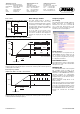
Temperature compensation
The conductivity or resistance of aqueous
solutions often depends greatly on the
temperature. The instrument provides the
following procedures for temperature
compensation, depending on the display size:
• Off (e.g. USP)
•Linear
•ASTM
• Natural waters (EN 27888/ISO 7888)
Analog input for main board
0(4) to 20 mA; 0 to 10 V and Pt100/Pt1000/
NTC/PTC (max. 30 kΩ)/cust. specs.
Typical application: Compensation input for
temperature compensation of the main
measurement variable.
Function modes of the input
options, "Multi-channel mode"
If analog inputs have been fitted (optional
board), the device will have multi-channel
functions. The following signal types can be
processed:
•0(4)to20mA
•0to10V
• Pt100/Pt1000
Sensors that return one of the output signals
listed above can be connected to the
instrument for the following measurement
variables, for example:
• free chlorine, chlorine dioxide, ozone,
hydrogen peroxide and peracetic acid as
per data sheet 202630.
• pH value or redox potential as per data
sheet 202705.
• Liquid level measurements.
• Flow rate measurements etc.
The instrument provides the following
calibration options in this function mode:
•Zero point
• Limit value
• Zero point and limit value
• Cell constant
• Temperature coefficient
This allows optimum adaptation of the
instrument to the sensor.
Linear scaling
Select this mode when the input signal will be
displayed linearly.
One of the following units is used for display
or control:
•µS/cm
•mS/cm
•%
•mV
•pH
• ppm
• Cust. specs. (5 characters)
Electrolytic conductivity
µS/cm or mS/cm are the units used for
display and control.
Specific resistance (ultra-pure water)
Display/control with the unit kΩ ×cm or
MΩ ×cm.
TDS
Display/control with the unit ppm.
The specific TDS factor can also be entered in
this mode.
Concentration
In this mode, the concentration of a liquid can
be determined from its uncompensated
conductivity.
% or "Cust. specs." are the units used for
display and control.
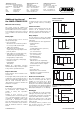
Concentration measurement:
Cust. specs. with table
Non-linear correlations between the input and
output variable can be processed in this
mode. Typical applications include measuring
the level of liquid in horizontal, cylindrical
containers or simply measuring the
concentration.
The input values are processed in a table
(max. 20 value pairs). Values can only be
entered in the table using the optional setup
program.
The units used for display and control are:
•µS/cm
•mS/cm
• Cust. specs. (5 characters)
• Use the offset parameter to adjust the
display.
Calibration
Calibration logbook
The last five successful calibrations can be
accessed from the calibration logbook. This
makes it possible to evaluate the aging of the
connected sensor.
The logbook can be deleted if necessary
(useful when changing the sensor).
If a datalogger has been fitted (optional
board), additional information such as the
date and time are documented.
Calibration timer
The calibration timer indicates (on request) a
required routine calibration. The calibration
timer is activated by entering the number of
days that must expire before there is a
scheduled re-calibration (specified by the
system or the operator).
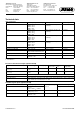
Caustic solution
NaOH 0to15% by wt. 0to90°C
NaOH 25 to 50 % by wt. 0 to 90 °C
Nitric acid
HNO
3
0to25% by wt. 0to80°C
HNO
3
36 to 82 % by wt. -20 to 80 °C
Sulfuric acid
H
2
SO
4
0to28% by wt. 0to100°C
H
2
SO
4
36 to 85 % by wt. 0 to 115 °C
H
2
SO
4
92 to 99 % by wt. 0 to 115 °C
Hydrochloric acid
HCl 0to18% by wt. 0to65°C
Hal 22 to 44 % by wt. -20 to 65 °C