JUMO safetyM TB/TW Temperature limiter, temperature monitor nach DIN EN 14597 B 70.1160.
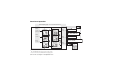
Overview of operation Normal display (appr ox. 5 secs after switch-on) P + Only available when C111=24 when Limit value C116 = 0 (factory setting) when C116 = 1 when C116 = 2 Measured value Warning alarm1 P Differential P P 2 2 when C116 = 4 Only available when C11* = 1 or 2 DIF – IN2 (differential of two Pt100 sensors in 2-wire circuit) 3 Access to this level can be inhibited with the Setup program. C111...C122 see Chapter 7 “Configuration level” P > 2 seconds Configuration level C111...
Contents Overview of operation . . . . . . . . . . . . . . . . . . . . . . . . . . . . . . . . . . . . . . . . . . . . . . . . . . . . . . . . 2 1 1.1 1.2 1.3 2 2.1 2.2 3 3.1 3.2 3.3 4 4.1 4.2 5 5.1 5.2 5.3 5.4 5.5 6 Brief description . . . . . . . . . . . . . . . . . . . . . . . . . . . . . . . . . . . . . . . . . . . . . . . . . . . . . . . . . . . . . 4 Temperature monitor (TW) . . . . . . . . . . . . . . . . . . . . . . . . . . . . . . . . . . . . . . . . . . . . . . . . . . . . . .
7.1 7.2 7.3 7.4 7.5 7.6 7.7 7.8 7.9 7.10 7.11 7.12 7.13 8 8.1 8.2 8.3 8.4 8.5 8.6 8.7 8.8 8.9 8.10 9 C111 Analog inputs . . . . . . . . . . . . . . . . . . . . . . . . . . . . . . . . . . . . . . . . . . . . . . . . . . . . . . . . . . C112 Setting for a double thermocouple . . . . . . . . . . . . . . . . . . . . . . . . . . . . . . . . . . . . . . . . . . C113 Unit, decimal place . . . . . . . . . . . . . . . . . . . . . . . . . . . . . . . . . . . . . . . . . . . . . . . . . . . . . .
Contents 9.1 9.2 9.3 10 10.1 10.2 10.3 10.4 11 Probes for operation in air . . . . . . . . . . . . . . . . . . . . . . . . . . . . . . . . . . . . . . . . . . . . . . . . . . . . . Probes for operation in water and oil . . . . . . . . . . . . . . . . . . . . . . . . . . . . . . . . . . . . . . . . . . . . . Probes for operation in air, water and oil . . . . . . . . . . . . . . . . . . . . . . . . . . . . . . . . . . . . . . . . . . Setup program . . . . . . . . . . . . . . . . . . . . . . . . . . . . . . .
2014-06-12 1 1 Brief description 4 Brief description Temperature limiters (TB) and temperature monitors (TW) are used to monitor thermal processes in systems, to signal whenever the measurement exceeds or falls below an adjustable limit value. This limit infringement is indicated by built-in LED K1 and the fitted relay switches the system to a safe operating state (alarm range). 1.
2 Identifying the instrument version The nameplate is glued to the side of the housing. AC supply: DC supply: The supply voltage must correspond to the voltage given on the nameplate! Please read these operating instructions before commissioning the instrument. These operating instruction are valid from instrument software version: 237.02.01 (Press + ). Keep the manual in a place which is accessible to all users at all times. Your comments could help us to improve these operating instructions.
2014-06-12 2 Identifying the instrument version Basic type 701160 Temperature limiter (TB) / temperature monitor (TW) Version 8 factory setting 9 configuration to customer specification Switching action 0151 0152 0153 0154 Inverse temperature monitor Direct temperature monitor Inverse temperature limiter Direct temperature limiter 001 003 005 006 024 037 039 040 041 042 043 044 Measurement input (programmable) Pt100 in 3-wire circuit Pt100 in 2-wire circuit Pt1000 in 2-wire circuit Pt1000 in 3-wire
045 046 048 052 053 063 071 601 Pt13Rh-Pt R Pt30Rh-Pt6Rh B NiCrSi-NiSi N 0 to 20 mA 4 to 20 mA 0 to 10 V 2 to 10 V KTY11-6 Supply 23 110 to 240 V AC +10% /-15%, 48 to 63 Hz 25 20 to 30V AC/DC, 48 to 63Hz 701160 / 8- 0153 - 001 - 23 factory setting 2.2 Scope of delivery - JUMO safetyM TB/TW in the ordered version - 1 Operating Instructions 701160.0 A All the required settings are described in the current operating instructions.
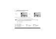
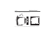
2014-06-12 3 3 Mounting and removal 8 Mounting and removal The instrument is clipped onto a 35 mm DIN rail (EN 60715) from the front. h Insert a screwdriver into the release slot, push towards the instrument and swing it downward, out of the DIN rail.
3.1 a a 3.2 a a 3.3 Mounting location Preferably vibration-free, so that screw terminals cannot work loose! Free from aggressive media, such as strong acids and caustic solutions and preferably free from dust and powder or other suspended matter, so that ventilation slots cannot get blocked up! Close mounting Maintain at least 10 cm of space at the top, so that the release slot can be accessed with a screwdriver from above. Several instruments can be mounted right next to one another, without a gap.
2014-06-12 4 4 Electrical connection 10 Electrical connection 4.1 A a a a a a a a a Installation notes The instrument is fitted with electronic components that can be destroyed by electrostatic discharge. It is therefore important during mounting, maintenance and servicing that personnel working on the instrument have adequate electrostatic discharge protection. All incoming and outgoing lines without a connection to the mains supply must be laid with shielded and twisted cables.
4.2 Connection diagram Screw terminals are used for connecting strands with a cross-section of 0.2 to 2.5mm2.
2014-06-12 4 Electrical connection Supply as on nameplate AC L1 External conductor N Neutral conductor DC L+ L- Analog inputs Thermocouple / double thermocouple (evaluated for temp. Limiter) Resistance thermometer in 2-wire circuit (evaluated for temp. Limiter) or KTY11-6 PTC in 2-wire circuit A Lead resistance must be entered for resistance thermometers in 2-wire circuit with longer cable lengths.
Analog inputs 0 to 20 mA 4 to 20 mA (evaluated for temp.
2014-06-12 5 5 Commissioning the instrument Commissioning the instrument 5.1 Displays and controls 14 h Apply the supply voltage, all segments light up four seconds long (for testing the segments). If everything is properly connected on the instrument, it will display the limit value, measured value or warning alarm, depending on the configuration. v If an alarm or error message appears, see Chapter 11 “Alarm messages”.
5.2 v 5.3 Display after switch-on The value to be displayed is adjustable, as in Chapter 7.6 “C116 Display after switch-on” Selecting and editing parameters (plausibility requirement for input values) Values are displayed in the normal display.
2014-06-12 5.4 Canceling editing + 5.5 5 Commissioning the instrument will cancel editing, the original value is retained.
2014-06-12 5 Commissioning the instrument 17
14-06-12 6 6 Parameter level 18 Parameter level This level is where to find the parameters AL, VA, ALD and DF, which are freely accessible to operating personnel at the factory. h In normal display, press for longer than 2 secs and AL will appear. This level can be inhibited by the setup program. v Chapter 10.
7 Configuration level All the configuration level parameters C111 - C122 are listed in the table below. Parameters that are not required are automatically blanked out. h In normal display, press for longer than 2 secs and AL will appear. h Press again for longer than 2 secs and C111 will appear. Each time you press , you move to the next parameter. All the parameters are freely accessible at the factory, but can be inhibited via the setup program. v Chapter 10.
2014-06-12 7.
Analog input Comment Setting range for AL: (can be restricted via setup) Limits for overrange/ underrange If the system is in the OK range, the relay is active and LED K1 shows green. If the system leaves the OK range, the relay switches off and LED K1 shows red.
2014-06-12 7 Configuration level Analog input Comment Setting range for AL: (can be restricted via setup) 22 Limits for overrange/ underrange 037 W3Re-W25Re D Thermocouple -1999 to +9999°C -5 039 Cu-CuNi T Thermocouple EN 60584 -1999 to +9999°C -205 to +405°C 040 Fe-CuNi J Thermocouple EN 60584 -1999 to +9999°C -205 to +1205°C 041 Cu-CuNi U Thermocouple DIN 43710 -1999 to +9999°C -205 to +605°C 042 Fe-CuNi L Thermocouple DIN 43710 -1999 to +9999°C -205 to +905°C 043 NiCr-Ni K
7.2 C112 Setting for a double thermocouple Double thermocouple Comment 0 no sensor short circuit not detected! 1 yes only available for C111 from 037 to 048 v Chapter 7.1 “C111 Analog inputs” Can detect a sensor short circuit 7.3 C113 Unit, decimal place Unit, decimal place Comment A 0 °C, no decimal place 1 °C, one decimal place 2 °F, no decimal place 3 °F, one decimal place 7.4 When the unit changes to °F, the measurement is converted.
2014-06-12 7.5 7 Configuration level C115 Switching action Switching action 0 24 inverse k Factory setting Comment If limit value AL is exceeded, the fitted relay switches OFF. LED K1 shows red and the limit flashes in the display. The temperature limiter remains in this state, even if the measured value falls below limit AL.
Switching action 1 direct A Comment If the value falls below limit AL, the fitted relay switches OFF. LED K1 shows red and the limit flashes in the display. The temperature limiter remains in this state, even if the measured value rises above limit AL. Only when a tool has been used to press the "Reset" key or if a switch has been operated by a relevant configuration of the binary input, does the relay switch back ON and LED K1 shows green.
2014-06-12 7.6 7 Configuration level C116 Display after switch-on Normal display Comment 0 Limit value Chapter “Overview of operation” 1 Measured value 2 Warning alarm 3 Limit for the differential 4 Differential 5 Measured value 2 7.7 Can only be set when C111 = 24 (differential measurement) is set.
7.8 C118 Display switch-off after timeout Display switch off Comment 0 inactive Display is permanently switched on. 1 active Display switches off after a timeout and re-appears, as soon as a key is pressed. 7.9 C119 Warning alarm function The warning alarm is indicated via LED KV and is output simultaneously at the binary output. The switching action can be configured as an absolute value or as an interval to the limit value (relative).
2014-06-12 7 Configuration level 28 7.
7.12 C 121 Count for relay switching operations Meaning Value range (factory setting in bold) Count for relay switching operations 0 to 9999 This is the actual counted amount of switching operations for the relay. If the limit-value set under C120 (factory setting 1000) is reached, error message 0001 is displayed and the relay is deenergized. If this error is acknowledged, counting starts again from 0. 7.
2014-06-12 8 Technical data 8 Technical data 8.1 Analog inputs Resistance thermometers Designation Measuring range Accuracy1 Pt 100 EN 60751 -200 to +850°C 0.1% KTY11-6 PTC -50 to +150 °C 1% Pt 1000 EN 60751 -200 to +850°C 0.
NiCrSi-NiSi N EN 60584 -100 to +1300°C 0.4% Pt10Rh-Pt S EN 60584 0 to +1768°C 0.4% Pt13Rh-Pt R EN 60584 0 to +1768°C 0.4% Pt13Rh-Pt6Rh B EN 60584 300 to 1820°C 0.4% W3Re-W25Re D 0 to +2495°C 0.4% Cold junction Pt 100, internal Cold junction accuracy ± 1K Sampling 210 ms Input filter 2nd order digital filter; filter constant adjustable from 0 to 100secs Features also programmable in °F 1. Accuracy refers to the maximum extent of the measuring range.
2014-06-12 8.2 8 Technical data 32 Measuring circuit monitoring RTD temperature probe Twin thermocouples Thermocouples and KTY11-6 Overrange underrange and is detected Probe break lead is detected and Current 0 to 20 mA, 4 to 20mA Voltage 0 to 10 V, 2 to 10 V LEDs K1 and KV light up; "9999" flashes in the display Probe short circuit is detected at 4 to 20mA LEDs K1 and KV light up; "9999" flashes in the display; relay K1 is and 2 to 10V inactive.
8.3 Binary input Connection Function 1 floating contact Configurable unlocking, keyboard inhibit, level inhibit 8.4 Binary outputs 1 relay 1 Binary output 8.5 10,0000 operations at a contact rating of 3A/230V, 50Hz resistive load Contact protection circuit: safety fuse 3.15AT, installed in the pole contact arm within the instrument 24 V DC / 20mA logic signal, short-circuit proof Supply Supply 20 to 30V AC/DC, 48 to 63Hz Power consumption 110 to 240 V AC +10/-15%, 48 to 63Hz 5 VA 8.
2014-06-12 8.7 8 Technical data Electrical safety Clearances / creep paths Mains to electronic components and probe Mains to the relay Relay to electronic components and probe ≥ 6 mm / ≥ 8 mm ≥ 6 mm / ≥ 8 mm ≥ 6 mm / ≥ 8 mm Electrical safety according to DIN EN 14597 (DIN EN 60730-2-9) Overvoltage category III, pollution degree 2 Protection type I with internal separation to SELV current circuits 8.
8.9 Housing Material polyamide (PA 6.6) Screw terminal 0.2 to 2.5mm2 screw terminal Mounting on 35mm x 7.5mm DIN rail to EN 60715 Operating position vertical Weight approx. 160g Protection IP 20 to EN 60529 8.
2014-06-12 9 DIN-approved probes 9 DIN-approved probes 9.1 Probes for operation in air 36 Note: Because of the high response accuracy, the use of thermowells (pockets) is not admissible. Actual type designation Old type designation Probe type Temperature range Nom. length mm - 1 x Pt100 -170 ... +700°C 500 1 x Pt100 -170 ... +700°C 500 2 x Pt100 -170 ... +700°C 500 Process connection RTD temperature probe Data Sheet 90.
901006/66-953-1046-6-250-668/000 9.2 90.027 1 x PT30Rh-PT6Rh, TypE „B“ 600 ... 1500°C 250 901006/66-953-1046-6-355-668/000 90.028 355 901006/66-953-1046-6-500-668/000 90.029 500 901006/66-953-2046-6-250-668/000 90-D-027 901006/66-953-2046-6-355-668/000 90-D-028 355 901006/66-953-2046-6-500-668/000 90-D-029 500 2 x PT30Rh-PT6Rh, TypE „B“ 600 ...
2014-06-12 9 DIN-approved probes 38 Note: Because of the high response accuracy, only use thermowells (pockets) that are included in the scope of delivery. Actual type designation Old type designation Probe type Temperature range Nom. length mm 902006/53-505-2003-1-12-190-815/000 90D239-F03 2 x Pt100 -40 ... +400 °C 190 902006/53-507-2003-1-12-100-815/000 90.239-F02 -40 ... +480 °C 902006/53-507-2003-1-12-160-815/000 90.
9.3 Probes for operation in air, water and oil Note: Because of the high response accuracy, the use of thermowells (pockets) is not admissible. Actual type designation Old type designation Probe type Temperature range Install. length mm 90.210-F95 1 x Pt100 max. 300°C 250 Process connection RTD temperature probe Data Sheet 90.2006 90.2006/10-390-1003-1-8-250-104/000 Thermocouples Data Sheet 90.1006 901006/45-551-2043-2-xxxx-11-xxxx A 2 x NiCr-Ni, TypE „K“ max. 1 50°C 50...
2014-06-12 9 DIN-approved probes 40
10 Setup program This program and the interface with adapter can be supplied as accessories. They offer the user the following advantages: - easy and convenient parameterization and archiving from a PC - simple duplication of parameters for instruments of the same type 10.
2014-06-12 10 Setup program 42 10.3 Activating the access code The factory setting is for no level inhibit to be active in the instrument. The access code can only be activated by the Setup program. h In the Setup program, enter a different value to "0" for the access code and transfer it to the instrument Now the parameter level and the configuration level on the device are only accessible with the correct access code.
11 Alarm messages The following alarm messages can be shown in alternation with the temperature display: Alarm display Cause Remedy 9999 flashes Gone above measured value The measured value is too large, is outside the range, or a probe has broken. h Check probe and connecting cable for damage or Gone below measured value The measured value is too small, is outside the range, or a probe shortcircuit has occurred. 2014-06-12 short-circuit v Chapter 4.
2014-06-12 12 12 Error messages 44 Error messages Error display (code) Cause Remedy The total number of relay switching operations has been reached. h Increase the total number of relay switching operations Chapter 7.11 “C 120 Limit value for relay switching operations” v h Acknowledge with the Reset key v Chapter 7.
0008 reserved - 0009 Calibration data checksum The instrument must be returned to JUMO for repair. 0010 Configuration data checksum h Send the instrument in v Chapter 2.
2014-06-12 13 13 What if... 46 What if... Description This appears display: Cause on the The Setup program is transferring data. The monitoring function switches off briefly during data transmission and the instrument restarts. The measurement in the The instrument is in the alarm range The measured value flashes in the display and upper display flashes. depending on which switching action is set (direct or inverse), is above or below the limit.
Description Cause Relay contact between terminals 9, 10 or 9, 12 does not switch. The fitted safety fuse in the pole arm 9 is faulty. Double LED lit (green and red simultaneously) Internal system error Remedy h Measure terminals 9 and 10 of the relay with a continuity tester when LED K1 shows green. h Measure terminals 9 and 12 of the relay with a continuity tester when LED K1 is off h The instrument must be returned to JUMO for repair. v Chapter 2.
2014-06-12 13 What if...
JUMO GmbH & Co. KG JUMO Instrument Co. Ltd. JUMO Process Control, Inc. Street address: Moritz-Juchheim-Straße 1 36039 Fulda, Germany Delivery address: Mackenrodtstraße 14 36039 Fulda, Germany Postal address: 36035 Fulda, Germany Phone: +49 661 6003-0 Fax: +49 661 6003-607 E-mail: mail@jumo.net Internet: www.jumo.net JUMO House Temple Bank, Riverway Harlow - Essex CM20 2DY, UK Phone: +44 1279 63 55 33 Fax: +44 1279 63 52 62 E-mail: sales@jumo.co.uk Internet: www.jumo.co.