
Operating Manual Owner manual


Table Of Contents
- Operating overview
- 1 Brief description
- 2 Identifying the device version
- 3 Mounting
- 4 Electrical connection
- 5 Startup of the device
- 5.1 Display and control elements
- 5.2 Setting the display after device is switched on
- 5.3 Selecting and editing parameters (plausibility requirement for input values)
- 5.4 Canceling edit
- 5.5 Acknowledging alarms using the reset key (for temperature limiter STB only)
- 5.6 Acknowledgement of alarms using the binary input (for temperature limiter STB only)
- 5.7 Functional test
- 5.8 Seal device
- 6 Safety Manual
- 6.1 Brief description
- 6.2 Safety temperature monitor (STW)
- 6.3 Safety temperature limiter (STB)
- 6.6 Connection possibilities of the sensors (SIL)
- 6.7 Standards and definitions
- 6.8 Safety-related parameters related to the temperature monitoring unit
- 6.9 Determining the Safety Integrity Level (SIL)
- 6.10 Determining the achieved Performance Level (PL)
- 6.12 Performance Level
- 6.13 Relationship between the Performance Level (PL) and the Safety Integrity Level (SIL)
- 6.14 Other applicable device documentation
- 6.15 Behavior during operation and in the event of a fault
- 6.16 Regular tests
- 6.17 Intrinsic safety according to DIN EN 60079-11
- 6.18 Monitoring of potential ignition sources according to DIN EN 50495 and DIN EN 13463- 6
- 6.19 Certificates
- 7 ATEX
- 7.1 Intended use
- 7.2 Identification markings according to ATEX directive 94/9/EC:
- 7.3 Meaning of the letter X in the type test certificate
- 7.4 Associated intrinsically safe electrical apparatus according to EN 60079-11
- 7.5 Safety device according to EN 50495
- 7.5.1 Temperature monitoring unit based on ignition protection "e" – increased safety according to EN 60079-7
- 7.5.1.1 Function of increased safety
- 7.5.1.2 Application in the 1-sensor variant
- 7.5.1.3 Application in the 2-sensor variant
- 7.5.1.4 Application of temperature transmitters
- 7.5.2 Minimum overpressure monitoring for static pressurized enclosure on the basis of ignition protection "p", pressurized enclosure according to EN 60079-2
- 7.5.2.1 Function of the static pressurized enclosure
- 7.5.2.2 Safety device for static pressurized enclosure
- 7.5.2.3 Application as safety device for static pressurized enclosure
- 7.6 Monitoring of potential ignition sources "b" according to EN 13463-6
- 8 Configuration level
- 9 Technical data
- 9.1 Analog inputs
- 9.2 Analog output
- 9.3 Binary input
- 9.4 Relay outputs
- 9.5 Measuring circuit monitoring
- 9.6 Voltage supply
- 9.7 Test voltages according to EN 60730, Part 1
- 9.8 Electrical safety
- 9.9 Environmental influences
- 9.10 Case
- 9.11 Approvals/approval marks
- 9.12 Important information for the probes in Chapter 9.13 to Chapter 9.15
- 9.13 Probes for the operating medium air
- 9.14 Probes for water and oil
- 9.15 Probes for air, water, and oil
- 10 Setup program
- 11 Alarm messages
- 12 Error messages
- 13 What to do, if ...
- 14 Information for devices with extra code 062 GL
- 15 Behavior of outputs
7 ATEX
2013-04-01
76
7.4.3 Explanation of probe temperature classes
The listed probes can be used in temperature classes T1 to T6.
Temperature classes
Item 26.5.1.3 in EN 60079-0:2009 stipulates a safety margin for type-tested devices of Group II (potentially explosive gas atmo-
spheres excluding mines susceptible to firedamp) of 10 K for the highest measured surface temperature for T1 and T2, and 5 K
for T3, T4, T5, and T6.
In the case of RTD temperature probes, a measuring current flows through the sensor element, which causes a rise in temper-
ature. In addition, a fault in the JUMO safetyM STB/STW Ex means that the sensor circuit may introduce a maximum output of
61.8 mW to the probe. This also applies to the thermocouple probes.
The maximum rise in temperature was determined through measurements.
The following values represent the worst case scenario and apply for all probes:
The maximum temperature rise of Pt100 probes is 7.5 K.
The maximum temperature rise of thermocouple probes is 0.9 K.
1. The following safety margins must also be observed:
Category 1: Acc. to EN 1127-1:2011 Item 6.4.2 (hot surfaces), the surface temperatures of all devices ... for use in zone 0..., that may come into contact with poten-
tially explosive atmospheres, … must not exceed 80 % of the ignition temperature.
This means the temperature class, minus 20 %.
As described above, in temperature classes T1 and T2, 10 °C must be deducted and in temperature classes T3 to T6, 5 °C must be deducted.
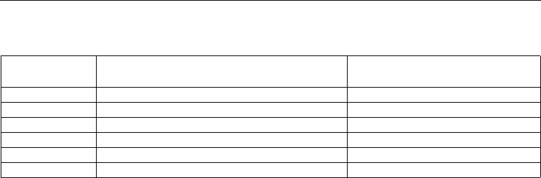
Table 17: Temperature classes
Temperature class
Maximum surface temperature of apparatus
1
Ignition temperature of the flammable
materials
T1 450 °C > 450 °C
T2 300 °C > 300 < 450 °C
T3 200 °C > 200 < 300 °C
T4 135 °C > 135 < 200 °C
T5 100 °C > 100 < 135 °C
T6 85 ? > 85 < 100 °C