
Operating Manual Owner manual


Table Of Contents
- Operating overview
- 1 Brief description
- 2 Identifying the device version
- 3 Mounting
- 4 Electrical connection
- 5 Startup of the device
- 5.1 Display and control elements
- 5.2 Setting the display after device is switched on
- 5.3 Selecting and editing parameters (plausibility requirement for input values)
- 5.4 Canceling edit
- 5.5 Acknowledging alarms using the reset key (for temperature limiter STB only)
- 5.6 Acknowledgement of alarms using the binary input (for temperature limiter STB only)
- 5.7 Functional test
- 5.8 Seal device
- 6 Safety Manual
- 6.1 Brief description
- 6.2 Safety temperature monitor (STW)
- 6.3 Safety temperature limiter (STB)
- 6.6 Connection possibilities of the sensors (SIL)
- 6.7 Standards and definitions
- 6.8 Safety-related parameters related to the temperature monitoring unit
- 6.9 Determining the Safety Integrity Level (SIL)
- 6.10 Determining the achieved Performance Level (PL)
- 6.12 Performance Level
- 6.13 Relationship between the Performance Level (PL) and the Safety Integrity Level (SIL)
- 6.14 Other applicable device documentation
- 6.15 Behavior during operation and in the event of a fault
- 6.16 Regular tests
- 6.17 Intrinsic safety according to DIN EN 60079-11
- 6.18 Monitoring of potential ignition sources according to DIN EN 50495 and DIN EN 13463- 6
- 6.19 Certificates
- 7 ATEX
- 7.1 Intended use
- 7.2 Identification markings according to ATEX directive 94/9/EC:
- 7.3 Meaning of the letter X in the type test certificate
- 7.4 Associated intrinsically safe electrical apparatus according to EN 60079-11
- 7.5 Safety device according to EN 50495
- 7.5.1 Temperature monitoring unit based on ignition protection "e" – increased safety according to EN 60079-7
- 7.5.1.1 Function of increased safety
- 7.5.1.2 Application in the 1-sensor variant
- 7.5.1.3 Application in the 2-sensor variant
- 7.5.1.4 Application of temperature transmitters
- 7.5.2 Minimum overpressure monitoring for static pressurized enclosure on the basis of ignition protection "p", pressurized enclosure according to EN 60079-2
- 7.5.2.1 Function of the static pressurized enclosure
- 7.5.2.2 Safety device for static pressurized enclosure
- 7.5.2.3 Application as safety device for static pressurized enclosure
- 7.6 Monitoring of potential ignition sources "b" according to EN 13463-6
- 8 Configuration level
- 9 Technical data
- 9.1 Analog inputs
- 9.2 Analog output
- 9.3 Binary input
- 9.4 Relay outputs
- 9.5 Measuring circuit monitoring
- 9.6 Voltage supply
- 9.7 Test voltages according to EN 60730, Part 1
- 9.8 Electrical safety
- 9.9 Environmental influences
- 9.10 Case
- 9.11 Approvals/approval marks
- 9.12 Important information for the probes in Chapter 9.13 to Chapter 9.15
- 9.13 Probes for the operating medium air
- 9.14 Probes for water and oil
- 9.15 Probes for air, water, and oil
- 10 Setup program
- 11 Alarm messages
- 12 Error messages
- 13 What to do, if ...
- 14 Information for devices with extra code 062 GL
- 15 Behavior of outputs
6 Safety Manual
41
2013-04-01
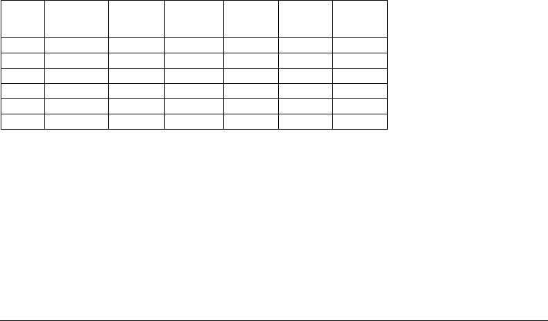
6.8.2 Failure rates and SFF for type 701155/X-XX-025X-XXXX-25 (AC/DC 24 V)
Important information:
Variants 1 to 4 were evaluated with JUMO probes according to data sheets 901006 and 902006.
For variant 5 no sensor system was included (only the JUMO safetyM STB/STW Ex).
In this case, the plant operator selects the sensor system.
The PFH and PFD
avg
values were calculated with the assumption that the time to restore the system is 8 h (MTTR = 72 h). Fur-
thermore, the calculation was based on a lifetime of 10 years (T
1
= 10 y). The Common Cause Factor was determined accord-
ing to the tables of DIN EN 61508 for sensor systems and logic.
Table 5:
Variant
λ
s
[Fit]
λ
dd
[Fit]
λ
du
[Fit]
SFF
PFH (1/h)
PFD
avg
1 919.23 306.82 34.24 96 % 7.22 e
-9
3.19 e
-4
1a 919.23 306.82 34.24 96 % 3.71 e
-9
1.63 e
-4
2 886.19 303.86 34.24 96 % 3.71 e
-9
1.63 e
-4
3 947.18 325.86 37.89 96 % 3.75 e
-9
1.64 e
-4
4 953.24 350.21 40.59 96 % 3.85 e
-9
1.69 e
-4
5 938.89 323.57 36.89 96 % 3.68 e
-9
1.61 e
-4