
Operating Manual Owner manual


Table Of Contents
- Operating overview
- 1 Brief description
- 2 Identifying the device version
- 3 Mounting
- 4 Electrical connection
- 5 Startup of the device
- 5.1 Display and control elements
- 5.2 Setting the display after device is switched on
- 5.3 Selecting and editing parameters (plausibility requirement for input values)
- 5.4 Canceling edit
- 5.5 Acknowledging alarms using the reset key (for temperature limiter STB only)
- 5.6 Acknowledgement of alarms using the binary input (for temperature limiter STB only)
- 5.7 Functional test
- 5.8 Seal device
- 6 Safety Manual
- 6.1 Brief description
- 6.2 Safety temperature monitor (STW)
- 6.3 Safety temperature limiter (STB)
- 6.6 Connection possibilities of the sensors (SIL)
- 6.7 Standards and definitions
- 6.8 Safety-related parameters related to the temperature monitoring unit
- 6.9 Determining the Safety Integrity Level (SIL)
- 6.10 Determining the achieved Performance Level (PL)
- 6.12 Performance Level
- 6.13 Relationship between the Performance Level (PL) and the Safety Integrity Level (SIL)
- 6.14 Other applicable device documentation
- 6.15 Behavior during operation and in the event of a fault
- 6.16 Regular tests
- 6.17 Intrinsic safety according to DIN EN 60079-11
- 6.18 Monitoring of potential ignition sources according to DIN EN 50495 and DIN EN 13463- 6
- 6.19 Certificates
- 7 ATEX
- 7.1 Intended use
- 7.2 Identification markings according to ATEX directive 94/9/EC:
- 7.3 Meaning of the letter X in the type test certificate
- 7.4 Associated intrinsically safe electrical apparatus according to EN 60079-11
- 7.5 Safety device according to EN 50495
- 7.5.1 Temperature monitoring unit based on ignition protection "e" – increased safety according to EN 60079-7
- 7.5.1.1 Function of increased safety
- 7.5.1.2 Application in the 1-sensor variant
- 7.5.1.3 Application in the 2-sensor variant
- 7.5.1.4 Application of temperature transmitters
- 7.5.2 Minimum overpressure monitoring for static pressurized enclosure on the basis of ignition protection "p", pressurized enclosure according to EN 60079-2
- 7.5.2.1 Function of the static pressurized enclosure
- 7.5.2.2 Safety device for static pressurized enclosure
- 7.5.2.3 Application as safety device for static pressurized enclosure
- 7.6 Monitoring of potential ignition sources "b" according to EN 13463-6
- 8 Configuration level
- 9 Technical data
- 9.1 Analog inputs
- 9.2 Analog output
- 9.3 Binary input
- 9.4 Relay outputs
- 9.5 Measuring circuit monitoring
- 9.6 Voltage supply
- 9.7 Test voltages according to EN 60730, Part 1
- 9.8 Electrical safety
- 9.9 Environmental influences
- 9.10 Case
- 9.11 Approvals/approval marks
- 9.12 Important information for the probes in Chapter 9.13 to Chapter 9.15
- 9.13 Probes for the operating medium air
- 9.14 Probes for water and oil
- 9.15 Probes for air, water, and oil
- 10 Setup program
- 11 Alarm messages
- 12 Error messages
- 13 What to do, if ...
- 14 Information for devices with extra code 062 GL
- 15 Behavior of outputs
6 Safety Manual
2013-04-01
36
6.7 Standards and definitions
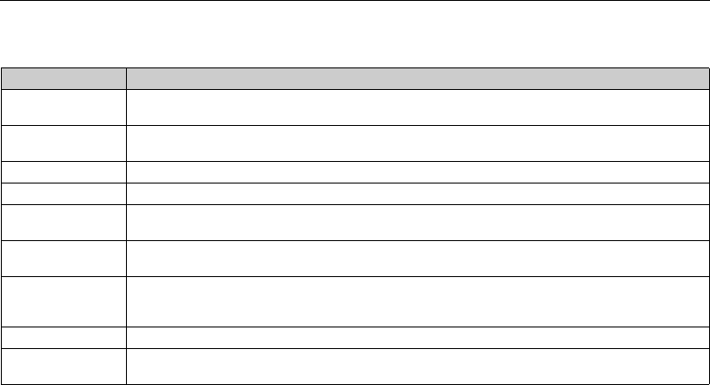
Table 2: Terms and abbreviations according to DIN EN 14597
Abbreviation Explanation
Type 2 Mode of operation for which the manufacturing variation and migration of the operating value, operat-
ing duration, or operating procedure has been checked.
Type B Micro disconnection in operation, corresponding contact disconnection at at least one pole to
provide functional reliability.
Type D A free trip mechanism that also cannot be closed temporarily for as long as the error persists.
Type F (STB) A mode of operation in which, after the RS has been installed, it can only be reset with the aid of a tool.
Type J (STB) A free trip mechanism with contacts that cannot be prevented from opening and which may not func-
tion as an automatically resetting RS if the means of resetting is held in the "Reset" or "On" position.
Type K A probe mode of operation in which a probe break or a disconnection between the probe head and the
switching head does not cause the operating value to increase.
Type N A mode of operation in which the operating value does not increase as a result of a leak in the probe or
in the parts that connect the probe and switching head. This mode is intended for use with electrical er-
ror models.
Type V (STB) A lockout that can only be reactivated through a manual reset.
Type P A mode of operation that is effective following a specified test through a change in temperature, as
specified in 17.101 of DIN EN 60730-2-9.