
Operating Manual Owner manual


Table Of Contents
- Operating overview
- 1 Brief description
- 2 Identifying the device version
- 3 Mounting
- 4 Electrical connection
- 5 Startup of the device
- 5.1 Display and control elements
- 5.2 Setting the display after device is switched on
- 5.3 Selecting and editing parameters (plausibility requirement for input values)
- 5.4 Canceling edit
- 5.5 Acknowledging alarms using the reset key (for temperature limiter STB only)
- 5.6 Acknowledgement of alarms using the binary input (for temperature limiter STB only)
- 5.7 Functional test
- 5.8 Seal device
- 6 Safety Manual
- 6.1 Brief description
- 6.2 Safety temperature monitor (STW)
- 6.3 Safety temperature limiter (STB)
- 6.6 Connection possibilities of the sensors (SIL)
- 6.7 Standards and definitions
- 6.8 Safety-related parameters related to the temperature monitoring unit
- 6.9 Determining the Safety Integrity Level (SIL)
- 6.10 Determining the achieved Performance Level (PL)
- 6.12 Performance Level
- 6.13 Relationship between the Performance Level (PL) and the Safety Integrity Level (SIL)
- 6.14 Other applicable device documentation
- 6.15 Behavior during operation and in the event of a fault
- 6.16 Regular tests
- 6.17 Intrinsic safety according to DIN EN 60079-11
- 6.18 Monitoring of potential ignition sources according to DIN EN 50495 and DIN EN 13463- 6
- 6.19 Certificates
- 7 ATEX
- 7.1 Intended use
- 7.2 Identification markings according to ATEX directive 94/9/EC:
- 7.3 Meaning of the letter X in the type test certificate
- 7.4 Associated intrinsically safe electrical apparatus according to EN 60079-11
- 7.5 Safety device according to EN 50495
- 7.5.1 Temperature monitoring unit based on ignition protection "e" – increased safety according to EN 60079-7
- 7.5.1.1 Function of increased safety
- 7.5.1.2 Application in the 1-sensor variant
- 7.5.1.3 Application in the 2-sensor variant
- 7.5.1.4 Application of temperature transmitters
- 7.5.2 Minimum overpressure monitoring for static pressurized enclosure on the basis of ignition protection "p", pressurized enclosure according to EN 60079-2
- 7.5.2.1 Function of the static pressurized enclosure
- 7.5.2.2 Safety device for static pressurized enclosure
- 7.5.2.3 Application as safety device for static pressurized enclosure
- 7.6 Monitoring of potential ignition sources "b" according to EN 13463-6
- 8 Configuration level
- 9 Technical data
- 9.1 Analog inputs
- 9.2 Analog output
- 9.3 Binary input
- 9.4 Relay outputs
- 9.5 Measuring circuit monitoring
- 9.6 Voltage supply
- 9.7 Test voltages according to EN 60730, Part 1
- 9.8 Electrical safety
- 9.9 Environmental influences
- 9.10 Case
- 9.11 Approvals/approval marks
- 9.12 Important information for the probes in Chapter 9.13 to Chapter 9.15
- 9.13 Probes for the operating medium air
- 9.14 Probes for water and oil
- 9.15 Probes for air, water, and oil
- 10 Setup program
- 11 Alarm messages
- 12 Error messages
- 13 What to do, if ...
- 14 Information for devices with extra code 062 GL
- 15 Behavior of outputs
12 Error messages
2013-04-01
124
12 Error messages
These error messages are displayed one below the other.
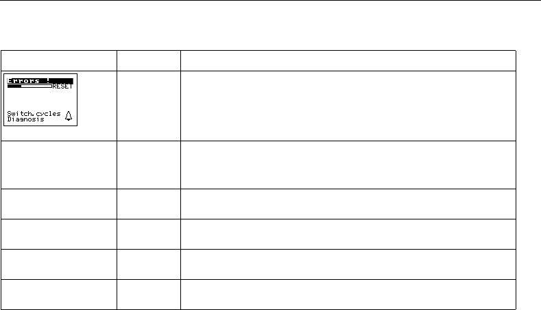
Error display (Err) Origin Cause/remedy
Internal The set limit value for relay switching cycles has been reached
h Increase the limit value for the relay switching cycles
v Chapter 8.7.1 "Limit switching cycle"
Instead of the bell, a cross appears and the error message can be acknowl-
edged.
Terminal temp. Internal The internal Pt100 is defective
1
, or the terminal temperature is outside the ad-
missible range (-10 to 80 °C).
This error cannot be acknowledged until it is within the admissible range
again.
Reference volt.
1
Internal The reference voltage is outside the valid range.
Acknowledgement is not possible until it is within the valid range again.
Calibration const.
1
Internal A calibration constant is outside the valid range.
Acknowledgement is not possible until it is within the valid range again.
Configuration Internal Configuration data outside the value range.
Acknowledgement is not possible until it is within the valid range again.
Measured value Internal The measured value 1 or 2 is outside the valid range.
Acknowledgement is not possible until it is within the valid range again.