
Datasheet

2014-09-01/00578870
Data sheet 703571 Page 5/21
JUMO GmbH & Co. KG Telefon: +49 661 6003-727
Hausadresse: Moritz-Juchheim-Straße 1, 36039 Fulda, Germany Telefax: +49 661 6003-508
Lieferadresse: Mackenrodtstraße 14, 36039 Fulda, Germany E-Mail: mail@jumo.net
Postadresse: 36035 Fulda, Germany Internet: www.jumo.net
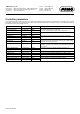
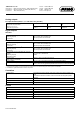
Controller parameters
The parameters and their meanings are listed in the table. Some parameters may be missing or meaningless for a particular type of controller.
Three-state controllers have two controller structures that can be parameterized differently for "heating" and "cooling." Four parameter blocks can
be managed for both of the controller channels.
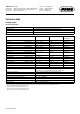
Parameters Value range Default setting Meaning
Proportional band Xp1 0 to 9999 digits 0 digits Size of the proportional band
The controller structure has no effect at 0!
In the case of a continuous controller, Xp1 and Xp2 must be > 0.
Proportional band Xp2 0 to 9999 digits 0 digits
Derivative time Tv1 0 to 9999 s 80 s Influences the differential component of the controller output signal
Derivative time Tv2 0 to 9999 s 80 s
Reset time Tn1 0 to 9999 s 350 s Influences the integral component of the controller output signal
Reset time Tn2 0 to 9999 s 350 s
Cycle time Cy1 0 to 999.9 s 20.0 s When using a switched output, the cycle time should be chosen so that
the energy supply to the process is as continuous as possible without
overloading the switching elements.
Cycle time Cy2 0 to 999.9 s 20.0 s
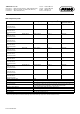
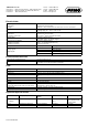
Contact spacing Xsh 0 to 999.9 digits 0.0 digits Spacing between the two control contacts for three-state controllers,
modulating controllers, and continuous controllers with integrated posi-
tion controller
Switching differential Xd1 0 to 999.9 digits 1.0 digit Hysteresis for switching controllers with proportional band = 0
Switching differential Xd2 0 to 999.9 digits 1.0 digit
Actuator time TT 5 to 3000 s 60 s Used run time range of the control valve for modulating controllers
Working point Y0 -100 to +100 % 0 % The output level for P and PD controllers (if x = w then y = Y0)
Output level limits Y1 0 to 100 % 100 % The maximum limit for the output level
Output value limits Y2 -100 to +100 % -100 % The minimum limit for the output level
Minimum relay ON time Tk1 0.000 to 60.00 s 0.000 s Limits the frequency of switching for switched outputs
Minimum relay ON time Tk2 0.000 to 60.00 s 0.000 s