
Datasheet


2014-09-01/00578870
Data sheet 703571 Page 13/21
JUMO GmbH & Co. KG Telefon: +49 661 6003-727
Hausadresse: Moritz-Juchheim-Straße 1, 36039 Fulda, Germany Telefax: +49 661 6003-508
Lieferadresse: Mackenrodtstraße 14, 36039 Fulda, Germany E-Mail: mail@jumo.net
Postadresse: 36035 Fulda, Germany Internet: www.jumo.net
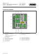
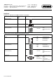
Connection diagram
The connection diagram included in the data sheet provides initial information about the connection options. Only use the installation instructions
or the operating manual for the electrical connection. The know-how and the correct technical implementation of the safety warnings/instructions
contained in these documents are the prerequisite for the installation, electrical connection, and initial start as well as for the safety during opera-
tion.
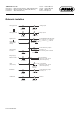
Analog inputs
Input IN8, IN9 as standard
Two analog inputs can be added to input (IN10), (IN11) optional boards
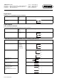
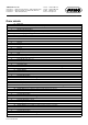
Analog outputs
One analog output can be added to output OUT 3/4 to 11/12 using optional boards
Connection (Connection ele-
ment)
Input
Symbol and terminal designation
Thermocouple (1) IN8
(2) IN9
(3) IN10
(4) IN11
3
4
RTD temperature probe
Two-wire circuit
2
4
RTD temperature probe
Three-wire circuit
2
3
4
Voltage DC 0(2) to 10 V 1
4
Voltage DC 0 to 1 V 2
4
Voltage DC 0 to 100 mV 3
4
Current DC 0(4) to 20 mA 3
4
Resistance transmitter
A = Start
E = End
S = Slider
2
3
4
Connection (Connection ele-
ment)
Input
Symbol and terminal designation
One analog output
DC0/2to10V or DC0/4to20mA
(configurable)
(8) OUT3/4
(9) OUT5/6
(10) OUT7/8
(11) OUT9/10
(12) OUT11/12
1
2
U
+
-
x
U
+
-
x
U
+
-
x
I
+
-
x
E
S
A
+
-
x
I
x
U
,