English Operating Manual Refrigerated and Heating Circulators FP45-HE 1.951.2462-V2 19512462-V2.doc 09/14 JULABO GmbH 77960 Seelbach / Germany Tel. +49 (0) 7823 / 51-0 Fax +49 (0) 7823 / 24 91 info@julabo.de www.julabo.de 22.09.
Congratulations! You have made an excellent choice. JULABO thanks you for the trust you have placed in us. This operating manual has been designed to help you gain an understanding of the operation and possible applications of our circulators. For optimal utilization of all functions, we recommend that you thoroughly study this manual prior to beginning operation.
HE TABLE OF CONTENTS Operating manual ................................................................................................................ 5 1. Intended use ................................................................................................................. 5 1.1. Description ............................................................................................................... 5 2. Operator responsibility – Safety recommendations .........................................
9.3. MENU PUMP - Setting of pump pressure ...............................................................38 9.4. MENU CONFIG - Configuration of unit ....................................................................39 9.4.1.Remote control via the serial interface ................................................................40 9.4.2.Keypad control or setpoint setting via the analog input .......................................41 9.4.3.AUTOSTART ...........................................................
HE Operating manual 1. Intended use JULABO circulators have been designed to control the temperature of specific fluids in a bath tank. The units feature pump connections for temperature control of external systems (loop circuit). JULABO circulators are not suitable for direct temperature control of foods, semiluxury foods and tobacco, or pharmaceutical and medical products. Direct temperature control means unprotected contact of the object with the bath medium (bath fluid). 1.1.
Operator responsibility – Safety recommendations 2. Operator responsibility – Safety recommendations The products of JULABO ensure safe operation when installed, operated, and maintained according to common safety regulations. This section explains the potential dangers that may arise when operating the circulator and also specifies the most important safety precautions to preclude these dangers as far as possible. The operator is responsible for the qualification of the personnel operating the units.
HE Use: The bath can be filled with flammable materials. Fire hazard! There might be chemical dangers depending on the bath medium used. Observe all warnings for the used materials (bath fluids) and the respective instructions (safety data sheets). Insufficient ventilation may result in the formation of explosive mixtures. Only use the unit in well ventilated areas. Only use recommended materials (bath fluids). Only use non-acid and non corroding materials.
Operator responsibility – Safety recommendations 2.1. Disposal The circulator contains a back-up battery that supplies voltage to memory chips when the unit is switched off. Do not dispose of the battery with household waste! Depending on battery regulations in your country, you might be obliged to give back used or defect batteries to gathering places. The product may be used with oil as bath fluid. These oils fully or partially consist of mineral oil or synthetic oil.
HE 2.3.
Operator responsibility – Safety recommendations 10
HE 2.4. Technical specifications Working temperature range Temperature stability Cooling capacity Medium: ethanol Refrigerant Overall dimensions Bath opening Bath depth Filling volume Weight Mains power connection Current draw Mains power connection Current draw cm cm cm liters kg FP45-HE -42 ... 200 ±0.01 +20 0 -20 -30 0.85 0.7 0.42 0.08 R-404A 38x58x69 23x26 20 18 ...
Operator responsibility – Safety recommendations Electrical connections: External alarm device 24-0 V DC / max. 25 mA Computer interface RS232 or RS485 External Pt100 sensor Optional for HE, SE (Order No.
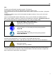
HE Operating instructions 3. 3.1. Safety notes for the user Explanation of safety notes In addition to the safety warnings listed, warnings are posted throughout the operating manual. These warnings are designated by an exclamation mark inside an equilateral triangle. “Warning of a dangerous situation (Attention! Please follow the documentation).” The danger is classified using a signal word. Read and follow these important instructions for averting dangers.
Safety notes for the user 3.3. Safety recommendations Follow the safety instructions to avoid personal injury and property damage. Also, the valid safety instructions for workplaces must be followed. • • • • • • • • • • • • • • • • • • • • • • • • • Only connect the unit to a power socket with an earthing contact (PE – protective earth)! The power supply plug serves as a safe disconnecting device from the line and must always be easily accessible.
HE Caution: The temperature controlling i.e. of fluids in a reactor constitutes normal circulator practice. We do not know which substances are contained within these vessels. Many substances are: • inflammable, easily ignited or explosive • hazardous to health • environmentally unsafe i.e.: dangerous The user alone is responsible for the handling of these substances! The following questions shall help to recognize possible dangers and to reduce the risks to a minimum.
Operating controls and functional elements 4. Operating controls and functional elements Front view Rear view 1a Mains power switch, illuminated for circulator 1b Mains power switch, illuminated for cooling machine 2 VFD COMFORT-DISPLAY Header: Control indicators Line 1: Actual value internal or external The display is depending on the selected control mode in the menu > Control < (internal or external). Line 2: Working temp. setpoint, constantly S xxx.
HE H U F Heater capacity in Watts Mains voltage Volts Flow rate in liters/minute (providing EPROG input set to >Flowrate<) *refer to >MENU/CONFIG< >CONFIG / ACTVAR> 2.1 Control indicators in the header: Heating / Cooling / Alarm / Remote control 2.2 2.3 Control indicators in the header: Temperature indication Internal or External actual value Temperature indication in °C (°F not possible on this unit) Display of set pump pressure stage Four stages, can be set via the key , under >MENU - PUMP<.
Operating controls and functional elements 6 Adjustable excess temperature protection according to IEC 61010-2-010 7 Socket for external measurement and control sensor or external setpoint programming ext Pt100 8 Interface RS232: remote control via personal computer SERIAL 9 Socket: control cable of JULABO refrigerated circulator or output for alarm messages Option: Electronic module 10 Order No.
HE 5. 5.1. Preparations Installation • Place the unit on an even surface on a pad made of nonflammable material. • The place of installation should be large enough and provide sufficient air ventilation to ensure the room does not warm up excessively because of the heat the instrument radiates to the environment. (Max. permissible ambient temperature: 40 °C).
Preparations Recommended bath fluids: Bath fluid soft/decalcified water mixture water/glycol, mixture 1:1 Temperature range 5 °C to 80 °C -20°C to 50°C JULABO bath fluids JULABO Description Order Number 10 liters 5 liters °C °C °C Temperature range Flash point Fire point Color JULABO Description Order Number 10 liters 5 liters °C °C °C Temperature range Flash point Fire point Color Thermal G 8 940 124 8 940 125 -30 ... 80 --light yellow Thermal HY 8 940 104 8 940 105 -80 ...
HE 5.3. Temperature application to external systems Caution: Securely attach all tubing to prevent slipping. If the circulator is operated without external system, close the pump connector (22) with the cap nut. Temperature application to external, closed systems The circulator is used for temperature application to external, closed systems (loop circuit) with simultaneous temperature application in the circulator bath.
Preparations Return flow safety device If the liquid levels in the circulator bath and the external system are at different heights, overflowing must be prevented after the power has been turned off. Flood hazard! For this reason, shut-off valves can be integrated in the loop circuit. Order No. 8 970 456 8 970 457 5.3.1. Description Shut-off valve (suitable up to +90 °C) Shut-off valve (suitable up to +200 °C) Tubing Recommended tubing: Order No.
HE 5.4. Filling / draining Notice: • • • Pay attention to the thermal expansion of bath oil during heating to avoid overflowing of the liquid. Do not drain the bath fluid while it is hot! Recommendation: Temperature range 5 °C to 40 °C Check the temperature of the bath fluid prior to draining (by switching the unit on for a short moment, for example). Store and dispose the used bath fluid according to the laws for environmental protection.
Operating procedures 6. 6.1. Operating procedures Power connection Caution: • • • • • Only connect the unit to a power socket with earthing contact (PE – protective earth)! The power supply plug serves as safe disconnecting device from the line and must be always easily accessible. Never operate equipment with damaged mains power cables. Regularly check the mains power cables for material defects (e.g. for cracks).
HE 6.2.2. Switching on the Cooling Machine Switching on: • Switch on the cooling machine using the switch (1b) . Control of the cooling machine: With the mains switch (1b) turned on, the circulator automatically switches the cooling machine off and on. • It is switched off, if: - the actual working temperature is increased by >30 °C (cooling is not required). - the heater operates at full power (>800 W) for longer than 5 minutes.
Setting of temperatures 7. 7.1. Setting of temperatures Using the pre-settings in the menu key to call up the menu for temperature selection. Press the 3 different working temperatures can be adjusted. Their values are freely selectable within the operating temperature range. The temperatures can be set in start or stop mode. Press key if a value is to be retained Setting of working temperature in the 1. Press the key Werkseinstellungen: SETPNT 1 25 °C SETPNT 2 37 °C SETPNT 3 70 °C menu .
HE 7.2. Direct setting of temperatures The circulator uses the setpoint of SETPNT 1 or 2 or 3 for temperature control The indicated setpoint temperature can be changed directly any time. Example: change 25.00 °C to 50.00 °C the circulator switches to the active 1. By pressing the key SETPOINT< example on the left: >SETPNT / 1 25.00°C<. The integer digits flash (example: <25>). and the value is changed to 2. By pressing the keys 50.00 °C and key.
Safety installations, warning functions 8. Safety installations, warning functions Check the safety installations at least twice a year! Refer to ( page 15) SECVAL (Security Values) SAFETMP AL-TYPE OVERTMP SUBTEMP 8.1. Settings for the excess temperature protection > SAFETMP< and for the warning functions for high > OVERTMP< and low > SUBTEMP< temperature are made in a menu which is called up by .
HE 8.1.1. Early warning system, low level protection This low level protection is independent of the control circuit and is divided into two sections: . 1. Switch in stage 1 recognizes a defined fluid level An audible warning sounds (interval tone) and together with the ticker: > LOW LEVEL WARNING-FILL MEDIUM < a message appears on the VFD COMFORT-DISPLAY: Refill the bath fluid! . 2.
Safety installations, warning functions 8.2. Switch-over from warning to shutdown function If a shutdown of functional elements (e.g. heater, circulating pump) is required when the limit values are exceeded or undercut the circulator can be changed over from warning function >WARNING< to shutdown function >ALARM<. Factory setting: >WARNING< . 1. Press the key 2. Select the menu >SECVAL -AL-TYPE< by pressing the 3. Press the key and the set parameter will flash (Example: WARNING) 4.
HE 8.3. Over and Sub temperature warning function Over temperature If the observance of a working temperature value >SETP< has to be supervised for a sensitive temperature application, then set over and sub temperature warning values. In the example below the SETPOINT 85 °C is surrounded by the values OVERTMP 87 °C and SUBTEMP 83 °C. The electronics immediately register if the actual temperature breaches one of the set limit values. The resulting reaction is defined in a further menu item.
Menu functions 9. Menu functions 1. Open the menu by pressing the 2. Use the 3. Press the Press the key. keys to scroll in menu level 1. key to change to menu level 2. key if settings are to be retained.
HE Menu level 1 Analog inputs/outputs Recorder output – CHANNEL 1, 2, 3 EPROG – External programmer input EX-STBY - STAND-BY input ALARM - output 9.1. Page 59 MENU PROGRAM – START This menu will start a previously set program. Requirements: 1. Create a program. (refer to next chapter) 2. Return to the Start-MENU and confirm the desired setting of each MENU item with the key 3. Set a start time (>TIME< >DATE< >YEAR<) if the program is to be started by the internal timer.
Menu functions Level 2 Parameter level • oer Confirm >NOW< with the will start immediately key and the program or start at the set time under parameter (TIMER ). Set time in the example below: 09. August 2009, 11:15 hrs set the time for the start of the program in the submenu >TIMER<.
HE The started program After the start the program will indicate the currently calculated setpoint in line 2 S XX.XX. The value increases within the time period >TSLICE< until the target temperature >SETPNT< of the section is reached. If the time period in a section is set to „0“, the next section will not begin until the target temperature has been reached. A B C1 C2 D1 to scroll to line 3.
Menu functions 9.2. MENU PROGRAM – creation, administration Menu level 1 1 program The integrated programmer permits fast and easy programming of setpoint temperature sequences. This temperature sequence is called program. A program is composed of individual sections (STEP). The sections are defined by duration (TSLICE) and target temperature. The target temperature is the setpoint (SETPNT), which is achieved at the end of a section.
HE Menu level 1 >EDIT< > DELETE< Create, administer program > STEP< Program step (1 ... 10) >SETPNT < Temperature setpoint of step ... >TSLICE< Duration of step ... delete program step (01 … 10, ALL) Level 2 Press key, if a parameter is to be retained.
Menu functions 9.3. MENU PUMP - Setting of pump pressure The pressure of the circulating pump is adjustable in four stages. After setting, the VFD COMFORT-DISPLAY indicates the corresponding value. Adjustable pump capacity Examples: Soll Illuminated display: Ist stage 1 ... 4 for pump pressure Adjusted:Display for the adjusted pump pressure stage in the –OFFmode. Effective: Display for the effective pump pressure stage (rotation speed) after start.
HE 9.4. MENU CONFIG - Configuration of unit Menu level 1 Level 2 A RESET can be effected only in the >OFF< mode. Switch off circulator by pressing the key and call up the menu CONFIGURATION. Parameter level • or Switch on and off remote control by pressing and Control display in the topline for Remote For remote control refer to 72 • or Press the key if a parameter is to be retained. Correction function for parameters and values (prior to OK). or Connect RS232 with PC.
Menu functions Level 2 Level 3 Parameter level • Hours flash, set by pressing • Minutes flash, set by pressing • Day flashes, set by pressing • Month flashes, set by pressing • Year flashes, set by pressing • Return to factory settings by pressing + + + + RESET returns all set values to the factory setting except for date and time. 9.4.1. + A RESET can be effected only in the –OFF- mode. During the message –RUN- all parameters are reset to factory settings.
HE 9.4.2. Keypad control or setpoint setting via the analog input Factory setting:: OFF The selected mode is indicated on the VFD COMFORT-DISPLAY OFF In addition to the serial interface via remote control the circulator offers the possibility to adjust the setpoint via analog interface >ext. Pt100< or >REG+E-PROG<. OFF - Setpoint setting with the navigation keys or the integrated programmer. PT100 - Setpoint setting via the analog socket „ext.
Menu functions 9.4.4. OFF-MODE Factory setting: PMP OFF or the Usually the circulating pump is controlled with the key start/stop command. If the circulating pump is to work in the –OFFmode, the adjustment can be set in a sub-menu. The pump motor will be shutdown in case of alarm anyhow. 9.4.5. ACTVAR - actuating variable Factory setting: CONTROL The variable (ACTuating VARiable) corresponds to the extent to which the heater or cooling unit of the circulator is controlled.
HE 9.4.6. Setting of clock and date The internal real time clock allows starting a program any time. The clock is set to the local mean time (MEZ) at the factory. 9.4.7. If the unit is operated in a different time zone, the clock can be adjusted in this menu. Change summer/winter time in this menu RESET – Factory settings A Reset will return all values to factory setting except for date and time. 9.5. A RESET can be effected in the >OFF< mode only.
Menu functions Level 2 Parameter level C-TYPE INTERNAL • The parameter flashes, switch by pressing and or • This parameter affects the temperature sequence in case of internal control. The parameter flashes, set by pressing + 0.1 … 99.9 • 3 … 9999 • The parameter flashes, set by pressing + The parameter flashes, set by pressing + 0 … 999 C-TYPE EXTERNAL • The parameter flashes, set by pressing + 0.1 … 99.
HE 9.5.1. CONTROL – Control INTERNAL / EXTERNAL Pt100 Switchover can only be effected if a Pt100 external sensor is connected. Factory setting: INT IMPORTANT: Additional measures for external temperature control Suggested settings for external temperature control: BAND HIGH / LOW and INTERN MAX / MIN see chapter >MENU LIMITS<. Sensor calibration of the Pt100 external sensor is carried out in the menu >ADJUST<, submenu >ATC SENOR - EXT<; set ATC STATUS< to >OFF< (See page 50).
Menu functions 9.5.2. SELFTUNING Selftuning: When performing a selftuning for the controlled system (temperature application system), the control parameters Xp, Tn and Tv are automatically determined and stored. Possible parameters: OFF - no selftuning The control parameters ascertained during the last identification are used for control purposes.
HE 9.5.4. Control parameters– XP-, TN-, TV- INTERNAL In most cases the control parameters preset in the factory are adequate for achieving an optimum temperature sequence. The control parameters allow adjustment to special control processes.. Proportional range >Xp< Setting range: 0.1 ... 99.9 The proportional range is the range below the setpoint in which the control circuit reduces the heating capacity from 100% to 0 % Reset time >Tn< (Integral component) Setting range: 3 ...
Menu functions 9.5.5. COSPEED - external This parameter affects the temperature pattern only in case of external control. Possible parameters: 0.0 ... 5.0 During selftuning, the control parameters Xp, Tn and Tv of a controlled system are automatically determined and stored. Depending on the controlled system, time for tuning can be unequally longer. This controller layout allows protection of sensitive objects requiring temperature application. °C Int. temperature Ext.
HE 9.6. MENU SERIAL - BAUDRATE, HANDSHAKE, PARITY Menu level 1 For communication between circulator and a PC or a superordinated process control system the interface parameters of both units must be identical. For remote control refer to page 72 Factory settings: 4800 Baud even hardware handshake Level 2 Parameter level • Press the retained.
Menu functions 9.7. MENU ATC - Absolut Temperature Calibration ATC serves to compensate a temperature difference that might occur between circulator and a defined measuring point in the bath tank because of physical properties. Principle: For ATC calibration, in steady state the bath temperature at the location of the temperature sensor (CT) is determined at the respective adjusted working temperature. This value is then set on the circulator in the menu >ATCalibration< under menu item > CTEMP X <.
HE Menu level 1 Level 2 Parameter level • Press the key if parameter is to be retained. Correction function for parameters or values (prior to OK). The parameter flashes, switch by pressing and or On level 2 a (I) is indicated for internal or an (E) for external. Example: • or The parameter flashes, switch by pressing and >NO< Carry out an ATC calibration >YES< return to standard operation after calibration.
Menu functions Level 2 Parameter level • Integer digits flash, set by pressing + • Decimal digits flash, set by pressing + If only a 2-point calibration is carried out, the following menu items are not indicated anymore The value is only indicated • • Integer digits flash, set by pressing + Decimal digits flash, set by pressing + 9.7.1. ATC SENSOR - INTERNAL / EXTERNAL In the first submenu the ATC function is set for the >INTERN< internal or the >EXTERN< external temperature sensor.
HE 9.7.3. CALIBRATION TYPE: 1 -/ 2 -/ 3 POINT A >1-point<, >2-point< or >3-point< calibration can be carried out. First geometrically define the location for calibration (measuring point CT), then determine the temperature values of the calibration points. The type of calibrations also determines the number of the following pairs of values indicated on the LCD DIALOG-DISPLAY.
Menu functions 9.7.4. Example: 3-point calibration for internal control In the temperature range from 80 °C to 160 °C the calibration curve of the temperature sensor (TT) is to be adjusted to the actual temperatures at measuring point (CT). 1. Set circulator to internal control: MENU CONTROL page 43 Menu level 1 The type of control can be set only in the –OFF- mode. 2.
HE • The parameter flashes, switch by pressing and . A >3-point< calibration is carried out. The value >TMPVAL< is only indicated In addition the measured value >CALVAL X< is saved during the following step • Integer digits flash, set by pressing (79) + • Decimal digits flash, set by pressing (70) + The first of 3 points is calibrated. Return to 2. Set working temperature value SETPNT: 120.
Menu functions 9.8. MENU LIMITS Menu level 1 Level 2 Parameter level Press the key if parameter is to be retained. Correction function for parameters or values (prior to OK).
HE 9.8.1. Limits for internal control SETPOINT MAX / MIN – Maximum and minimum setpoint Restriction of the adjustable temperature range. The limitation of the operating temperature range effects the temperature setting in the menu with the key . Only setting of working temperatures which lie within the determined limits is possible Existing settings for SETPNT 1, -2, -3, as well as those for >OVERTMP< and > SUBTMP < (refer to page 28), are automatically deferred into the limit range.
Menu functions BAND HIGH / LOW – Band limitation The band limitation is active during external control. Varied, practiceoriented setting are feasible for heat-up and cool-down phases. Setting range: 0 °C ... 200 °C BAND HIGH and BAND LOW allow for the limitation of the difference between the temperatures in the internal bath and the external system to any maximum value for the heat-up and cool-down phase. During the heat-up phase this difference value is always added to the actual external temperature.
HE 9.9. MENU IN/OUT – Analog inputs/outputs (Option) In order to use the analog inputs and outputs, the circulator must be equipped with the electronic module available as option. Order No. 8 900 100 Electronic module ALARM STAND-BY REG+ E-PROG This submenu enables setting of the input and output values for the programmer input and the temperature recorder outputs of socket REG+EPROG. The >STAND-BY< input and the >ALARM< output are configurable.
Menu functions Level 2 Level 3 Parameter level • • + • Integer digits flash, set by pressing + Decimal digits flash, set by pressing The parameter flashes, switch by pressing and • • Integer digits flash, set by pressing + Decimal digits flash, set by pressing + • The parameter flashes, switch by pressing and • The parameter flashes, switch by pressing and The parameter flashes, switch by pressing and Define the indication of or or VOLTAGE CURRENT 60
HE Level 2 Level 3 Parameter level • Lower VALue • Upper VALue • or Integer digits flash, set by pressing + Decimal digits flash, set by pressing + The parameter flashes, switch by pressing and • The parameter flashes, switch by pressing and • The parameter flashes, switch by pressing and 61
Menu functions 9.9.1. Outputs of the connector - REG+E-PROG REG+E-PROG : CHANNEL 3 EPROG CHANNEL 2 1. Select CHANNEL 1, 2 or 3 2. First define the desired output value for CHANNELs 1 to 3: CHANNEL 1 internal actual temperature value (bath temperature)) REG+E-PROG external actual temperature value (external sensor) periodic or intermittent heating or cooling 1. active setpoint temperature (SETPoint 1, 2, 3,/ integr. programmer /external programmer) 3.
HE 9.9.2. Input of the connector - REG+E-PROG CHANNEL 3 EPROG CHANNEL 2 Setting needs to be carried out, if 1. setpoint programming is to be made via an external voltage or current source or programmer. For this, in the menu > MENU / CONFIG < first set the menu item > SETP < to >EPROG<. CHANNEL 1 REG+E-PROG > > 2. the heater variable should be controlled via an external control pulse. For this, in the menu > MENU / CONFIG < set the menu item >ACTVAR< to >EPROG<. > > (refer to page 42). 3.
Menu functions Examples: 4. 5. – Setting the LOW value: (See below ) First adjust and set the lowest voltage or current on the external voltage or current source (e.g. 0 V or 0 mA). Then after approx. 30 secs enter the corresponding temperature value (e.g. 20.00 °C).on the circulator by pressing and – Setting the HIGH value: (See below ) First adjust and set the highest voltage or current on the external voltage or current source (e.g. 10 V or 20 mA). Then after approx.
HE Example out of diagram A: • Adjusting the voltage source for an output of 7.6 V! The instrument calculates this value from the rise angle of the two predecided end points (in example A: 7.6 V correspond to an external setpoint temperature of 152.0 °C ). After returning the VFD display to standard display, this value is displayed in line 2 (Example: SP 152.00 °C). Notice: If this adjustment is not correctly performed at two different points, the setpoint setting will be incorrect. 9.9.3.
Menu functions EX-STBY: External Stand-by input (for external switch-off) AK Possible parameters: 2 INACTIV - standby input is ignored ACTIV - standby input is active 3 1 Activate the standby input: 1. Under menu item > EXT-STBY <, set the parameter to >ACTIV<. 2. Connect an external contact ‚AK‘ (e.g. for switch-off) or an alarm contact of the superordinated system.
HE 10. Troubleshooting guide / error messages Alarm with complete shutdown: If one of the following failures occur a complete, all-pole shutdown of the heater and circulating pump is effected. + “ lights up and a continuous signal sounds. „ The code for the cause of alarm is indicated on the VFD COMFORTDISPLAY. Alarm without shutdown: The code for the cause of alarm is indicated on the VFD COMFORTDISPLAY. The warning signal sounds in regular intervals. The messages appear every 10 seconds.
Troubleshooting guide / error messages Error message with ticker: >SENSOR DIFFERENCE ALARM-CHECK VISCOSITY AND PUMP STAGE< Defect of working or excess temperature protector. Working temperature sensor and excess temperature protector report a temperature difference of more than 35 K. Error message with ticker: > INTERNAL HARDWARE ERROR-CALL SERVICE < Other errors Error in A/D converter Error message with ticker: > EXCESS TEMPERATURE PROTECTOR ALARM-CHECK ADJUSTMENT < Excess temperature protector defect.
HE Error message with ticker: > SAFETY SENSOR ALARM-CALL SERVICE < The cable of the excess temperature protector has been disconnected or short-circuited Ext. Pt100 sensor input without signal, but setpoint programming set to external Pt100. Error message with ticker: > LOW LEVEL WARNING-FILL MEDIUM < The early warning system for low level reports a critical fluid level. Refill bath fluid. By quickly switching off and restarting the unit the alarm is cancelled.
Electrical connections 11. Electrical connections Notice: Use shielded cables only. The shield of the connecting cable is electrically connected to the plug housing. The unit ensures safe operation if connecting cables with a maximum length of 3 m are used. The use of longer cables does not affect proper performance of the unit, however external interferences may have a negative impact on safe operation (e.g. cellular phones).
HE / Control output The connector may only be used for control of a JULABO refrigerated circulator or JULABO MVS Solenoid valve controller for cooling water. Pin assignment: Pin Signal (only with attached JULABO equipment) 1 +24 V (I max. current 25 mA) 2 0V 3 Alarm relay 4 Reserved - do not use! 5 Cooling pulse Alarm output (for external alarm signal) This potential-free change-over contact is activated in case of an alarm when pins 2 and 3 are connected.
Remote control 12. Remote control 12.1. Setup for remote control 5 9 1 6 RS232C 1. Check the interface parameters for both interfaces (on circulator and PC) and make sure they match. (Serial interface refer to page 49) 2. In the menu > MENU CONFIG < set the menu item to . 3. Connect both units with an interface cable.. Like all parameters which can be entered through the keypad, interface parameters are stored in memory even after the circulator is turned off. 12.2.
HE 12.3. List of commands out commands: Setting temperature values or parameters. Command Parameter Response of circulator out_mode_01 0 Use working temperature > SETPNT 1< out_mode_01 1 Use working temperature > SETPNT 2< out_mode_01 2 Use working temperature > SETPNT 3< out_mode_02 0 out_mode_02 1 out_mode_02 2 out_mode_03 0 out_mode_03 1 Selftuning „off“. Temperature control by using the stored parameters.
Remote control Command Parameter Response of circulator out_par_12 xxx Tv control parameter of the cascade controller. out_par_13 xxx Maximum internal temperature of the cascade controller. out_par_14 xxx Minimum internal temperature of the cascade controller. out_par_15 xxx Band limit (upper) 0 ... 200 °C out_par_16 xxx Band limit (lower) 0 ... 200 °C out_hil_00 -xxx out_hil_01 xxx Set the desired maximum cooling power (0 % to 100 %).
HE Command Parameter Response of circulator in_par_04 none in_par_05 none in_par_06 none CoSpeed - Band limit (max. difference between the temperatures in the internal bath and external system). Factor pk/ph0: Ratio of max. cooling capacity versus max. heating capacity Xp control parameter of the internal controller. in_par_07 none Tn control parameter of the internal controller. in_par_08 none Tv control parameter of the internal controller.
Remote control 12.4. Status messages Status messages Description 00 MANUAL STOP Circulator in „OFF“ state. 01 MANUAL START Circulator in keypad control mode. 02 REMOTE STOP Circulator in „r OFF“ state. 03 REMOTE START Circulator in remote control mode. 12.5. Error messages Error messages Description -01 LOW LEVEL ALARM Low liquid level alarm. -02 REFRIGERATOR ALARM Control cable of the refrigerated circulator or MVS solenoid valve controller short-circuited or interrupted.
HE Error messages Description -23 WARNING: HIGH TEMPERATURE ON COMPRESSOR STAGE 1 Excess temperature on compressor stage 1. -24 WARNING: HIGH TEMPERATURE ON COMPRESSOR STAGE 2 Excess temperature on compressor stage 2. -25 REFRIGERATOR WARNING Error in the cooling machine. -26 WARNING: STAND-BY PLUG IS MISSING External standby contact is open. (see page 65 and 71) -30 CONFIGURATION ERROR: The configuration of the circulator does not conform to its CONFIRM BY PRESSING ON present use.
JULABO Service – Online remote diagnosis 14. JULABO Service – Online remote diagnosis JULABO circulators of the HighTech series are equipped with a black box. This box is implemented in the controller and records all significant data for the last 30 minutes. In case of a failure, this data can be read out from the unit by using special software. This software is available as a free download from www.julabo.de \ EasyBlackBox. • Installation is easy and is performed step by step.
HE 15. Cleaning / repairing the unit Caution: • • • Always turn off the unit and disconnect the mains cable from the power source before cleaning the unit. Prevent humidity from entering into the circulator. Electrical connections and any other work must be performed by qualified personnel only. To maintain the full cooling performance, clean the condenser from time to time. • Switch off the unit, disconnect mains power cable. • Hold the venting grid, pull out and remove.