English Operating manual Recirculating Coolers FL20006 FLW20006 1.951.4837-V2 19514837-V2.doc 10/13 JULABO GmbH 77960 Seelbach / Germany Tel. +49 (0) 7823 / 51-0 Fax +49 (0) 7823 / 24 91 info@julabo.de www.julabo.de Print date: 09.10.
Congratulations! You have made an excellent choice. JULABO thanks you for the trust you have placed in us. This operating manual has been designed to help you gain an understanding of the operation and possible applications of our circulators. For optimal utilization of all functions, we recommend that you thoroughly study this manual prior to beginning operation.
TABLE OF CONTENTS 1. Intended use ................................................................................................................................. 4 1.1. Description ........................................................................................................................ 4 2. Operator responsibility – Safety instructions ................................................................................ 4 2.1. Installation Log for FL20006 ........................................
1. Intended use JULABO recirculating coolers have been designed for temperature application to specific fluids. The pump connections can be used for cooling applications in an external circuit at a constant temperature. JULABO water baths are not suitable for direct temperature control of foods, semiluxury foods and tobacco, or pharmaceutical and medical products. Direct temperature control means unprotected contact of the object with the bath medium (bath fluid). 1.1.
Safety recommendations for the operator You received a product developed for industrial use. Nevertheless, avoid strikes to the housing, vibrations, damages to the keypad foil (keys, display) or contamination. Make sure the product is regularly checked for proper condition. Regularly check (at least every 2 years) the proper condition of the mandatory, warning, prohibition and safety labels.
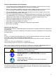
2.1. Installation Log for FL20006 EN 378-4:2008-06 Documentation 2.2. The operator is obliged to keep an installation log for the refrigeration unit if the filling volume of the refrigerant exceeds 3 kg! The installation log must be kept with the unit. If the information and data is recorded on a computer, the current status must be printed out (hard copy) and kept with the unit. It must be assured that the log is available to an expert in case of repairs and repeated inspections.
2.3.
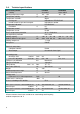
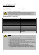
2.4. Technical specifications Recirculating Cooler Cooling Working temperature range Temperature stability Temperature selection: via key pad remote control via personal computer Temperature indication: Resolution Temperature control Temperature sensor Excess temperature protection Low liquid level protection Cooling capacity Medium: Mixture water-glycol Cooling compressor Refrigerant °C °C °C °C kW FL20006 FLW20006 air cooled water coolrd -25 ... +40 -25 … +40 ±0.
Warning functions and safety installations Excess temperature protection Low liquid level protection Alarm message Excess temperature - Warning function Overload protection Classification according to DIN 12876-1 85 °C - fixed value float switch optical + audible (permanent) 75 °C for compressor and pump motor class I Environmental conditions according to IEC 61 010-1: Use only indoor. Altitude up to 2000 m - normal zero. Ambient temperature: +5 ... +40 °C Air humidity: Max. rel.
2.5. Cooling water connection Only for water cooled models - FLW: Cooling water pressure (IN / OUT ) Difference pressure (IN - OUT ) Flow rate on FLW 20006 Cooling water temperature max. typical 6 bar 2 bar to 6 bar 24.
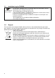
3. 3.1. Safety notes for the user Explanation of safety notes In addition to the safety warnings listed above, warnings are posted throughout the manual. These warnings are designated by an exclamation mark inside an equilateral triangle. “Warning of a dangerous situation (Attention! Please follow the documentation).” The danger is classified using a signal word. Read and follow these important instructions. Warning: Describes a possibly highly dangerous situation.
4. Make sure that the tubing is securely attached. Regularly check the tubing for material defects (e.g., for cracks). Never operate damaged or leaking equipment. Always turn off the unit and disconnect the mains cable from the power source before performing any service or maintenance procedures, or before moving the unit. Always turn off the unit and disconnect the mains cable from the power source before cleaning the unit. Always empty the bath before moving the unit.
Caution: Pump pressure Determine and check the max. admissible pressure for the external circuit before putting the unit into operation. The max. pressure is determined by the weakest element in the circuit (e. g. glass equipment). Securely attach all tubing to prevent slipping. Do not seal the overflow! Connect the tubings for cooling the external system to the pump connectors M16x1 for feed and return (14) on the rear of the recirculating cooler.
Return flow safety device If the filling volume of the bath tank is not sufficient, prevent the liquid from flowing back by using shut-off valves.. Order No. 8 970 458 Description Shut-off valve G 1¼“ Suitable for FL(W) 7006/11006/20006 The following questions shall help to recognize possible dangers and to reduce the risks to a minimum. Are all tubes and electrical cables connected and installed? Note: sharp edges, hot surfaces in operation, moving machine parts, etc.
5.
1 Mains power switch ON 2.0 Keypad, spash-water protected 2.1 Edit keys (set point increase or decrease) 2.2 Enter key Store set point value / parameter 3.0 Indication °C 3.1 LED temperature display 3.2 Control indicator – Cooling 3.
6. 6.1. Operating procedures Bath fluids Caution: No liability for use of other bath liquids! Please contact JULABO before using other than recommended bath fluids. JULABO takes no responsibility for damages caused by the selection of an unsuitable bath fluid Do not use alcohols. Water: The quality of water depends on local conditions. Due to the high concentration of lime, hard water is not suitable for temperature control because it leads to calcification in the bath.
6.3. Filling Take care that no liquid enters the interior of the circulating cooler. Top view Connect the tubing from the external system to the pump connectors and check for leaks Respect instructions from page 12 to page 14! Check to make sure that the drain taps (9a, 9b) are closed. H L 6.4. Unscrew the plug from the filling port (4). Fill in bath fluid up to marking „H“ of the filling level indicator. Turn the mains switch (1) on (Switching on - see below) for approx.
6.5. Setting the feed pressure max. Set the max. permissible feed pressure (example: 2 bar) by slowly closing the adjusting valve (13) on the rear and looking at the manometer (5). The max. pressure is determined by the weakest element in the circuit (e. g. glass equipment). 6.6. Setting the temperatures Factory setting: 6.7. 25 °C Setting can be carried out in the start/stop condition. 1. Press one of the keys for a short moment.
6.8. Remote control: activate – deactivate The recirculating cooler is to be prepared for remote control by a personal computer via the serial interface RS232. Set the interface item from >IOFF< to >ION<. Remote control: activate – deactivate: (Interface OFF) Switch off recirculating cooler by pressing the mains switch and wait approx. 5 seconds. (Interface On) Keep depressed the keys and enter simultaneously and turn on the unit with the mains power switch.
7. Safety installations 7.1. Excess temperature protection This safety installation is independent of the control circuit. When the temperature of the bath fluid has reached the safety temperature (85 °C), a complete shutdown of the compressor and pump is effected. The alarm is indicated by optical and audible signals (continuous tone) and on the LED-DISPLAY appears the error message "Error 14". + 7.2. Low level protection This safety installation is independent of the control circuit.
The return temperature is above the switch-off value of the high temperature protection (85°C). Check dimensioning of application. Use a stronger recirculating cooler if necessary. The motor protection switch for the compressor motor is off. Set motor protection switch to >1< . Check the fuses. The pressure sensor of low pressure side (evaporation pressure) is faulty, short-circuited or has a line interruption. Have the repair done by a specialist.
9. Electrical connections Notice: Use shielded cables only. The shield of the connecting cable is electrically connected to the plug housing. The unit ensures safe operation if connecting cables with a maximum length of 3 m are used. The use of longer cables does not affect proper performance of the unit, however external interferences may have a negative impact on safe operation.
10. Remote control 10.1. Setup for remote control 5 9 1 RS232 6 Check the interface parameters for both interfaces (on recirculating cooler and PC) and make sure they match. Interface parameters are pre-determined. Type Baudrate Parity Handshake RS232 4800 bauds even hardware handshake 10.2. Communication with a PC or a superordinated data system If the recirculating cooler is put into remote control mode the MULTI-DISPLAY (LED) will read „R -OFF-„ = REMOTE STOP.
The out commands are valid only in remote control mode. Examples: Command to set the working temperature to15,5 °C: Command to ask for the working temperature Response from the recirculating cooler: out_sp_00 15.5 in_sp_00 15.5 LF 10.3. List of commands out commands: Setting parameters or temperature values. Command Parameter Response of recirculating cooler out_mode_05 0 out_mode_05 1 Stop the unit = R –OFF-. Start the unit. out_sp_00 xxx.
10.5. Error messages Error messages Description -01 LOW LEVEL ALARM Low liquid level alarm. -05 WORKING SENSOR ALARM Working temperature sensor short-circuited or interrupted. -03 EXCESS TEMPERATURE WARNING High temperature warning. Starting at 75 °C (no deactivation) The return temperature soon reaches the switch-off value of the high temperature warning function (85 °C) -07 I2C-BUS ERROR Internal error when reading or writing the I2C bus. -08 INVALID COMMAND Invalid command.
11. Cleaning / repairing the unit Caution: Always turn off the unit and disconnect the mains cable from the power source before cleaning the unit. Prevent humidity from entering into the circulator. Electrical connections and any other work must be performed by qualified personnel only. Notice: Risk of hand injuries when mounting the venting grid. Maintaining the cooling performance Air cooled models = FL To maintain the full cooling performance, clean the condenser from time to time.
Cleaning: Clean the outside of the unit using a wet cloth and low surface tension water. The recirculating cooler is designed for continuous operation under normal conditions. Periodic maintenance is not required. The tank should be filled only with a bath fluid recommended by JULABO. To avoid contamination, it is essential to change the bath fluid from time to time.
11.1. JULABO Service – Online remote diagnosis JULABO circulators of the HighTech series are equipped with a black box. This box is implemented in the controller and records all significant data for the last 30 minutes. In case of a failure, this data can be read out from the unit by using special software. This software is available as a free download from www.julabo.com \ EasyBlackBox. Installation is easy and is performed step by step. Please observe the instructions.
11.2. Draining Notice: Store and dispose the used bath fluid according to the laws for environmental protection. Risk of injury for hands when mounting the venting grid. The unit has two drain taps. Both have to be used. First drain the large tank via drain tap A, the drain the remaining liquid via drain tap B. 30 Turn off the unit and disconnect the mains cable from the power source. Hold the venting grid, pull out and remove.
12. Warranty conditions JULABO GmbH warrants its products against defects in material or in workmanship, when used under appropriate conditions and in accordance with appropriate operating instructions for a period of ONE YEAR. Extension of the warranty period – free of charge With the ‘1PLUS warranty’ the user receives a free of charge extension to the warranty of up to 24 months, limited to a maximum of 10 000 working hours.
13.