
Instruction Manual
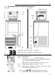
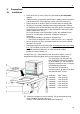

Operating controls and functional elements
16
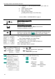
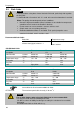
PS Capacity in % - with manipulated variable set to >serial<* or
>eprog<*
H Heater capacity in Watts
U Mains voltage Volts
F Flow rate in liters/minute
(providing EPROG input set to >Flow rate<)
*refer to >MENU / CONFIGIGURATIO> page 31
2.1
Control indicators in the header:
Heating / Cooling / Alarm /
Remote control
2.2
Control indicators in the header:
Temperature indication Internal or External actual value
Temperature indication in °C or °F
2.3
Display for the adjusted pump pressure stage in the -OFF- mode.
Display for the effective pump pressure stage (rotation speed) after start.
Four stages, adjustable via the
button, in the menu >PUMP<.
3
LCD DIALOG-DISPLAY
Line 1: Setpoint and origin of setpoint programming
(Key / RS232 or RS485 / ext. Pt100 / EProg)
Line 2: Actual value - internal or external,
identical to line 1 of the VFD-COMFORT-DISPLAY
Line 3: Heating capacity in %.
Line 4: Control type: internal / external
Navigation aid in MENU - Window
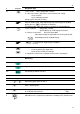
Keys
/ :
Selection of menu items / parameters
- Setting in line 3:
Actual value / parameter
Orientation aid in MENU - Window
Line 1 - name with allocation to key
Safety values
T – Setpoint
1 Main menu Level 1
2 Submenu Level 2
Example: CONFIGURATION
3 Submenu Level 3