English Operating manual Recirculating coolers FC1200S FC1600S FC1200T FC1600T FC600-T FC1200-T FCW1200S FCW1600S FCW1200T FCW1600T FCW2500T FC1600-T JULABO GmbH 77960 Seelbach / Germany Tel. +49 (0) 7823 / 51-0 Fax +49 (0) 7823 / 24 91 info@julabo.de www.julabo.de 1.951.4811-V2 19514811-V2.doc 06/13 26.07.
Congratulations! You have made an excellent choice. JULABO thanks you for the trust you have placed in us. This operating manual has been designed to help you gain an understanding of the operation and possible applications of our circulators. For optimal utilization of all functions, we recommend that you thoroughly study this manual prior to beginning operation.
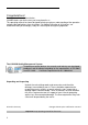
Recirculating coolers Table of Contents 1. Intended use............................................................................................... 4 1.1. 2. 2.1. 2.2. 2.3. 2.4. 2.5. 3. Explanation of safety notes ...................................................................... 14 Explanation of other notes ........................................................................ 14 Safety instructions ....................................................................................
Intended use 1. Intended use JULABO recirculating coolers have been designed for temperature application to specific fluids. The pump connections can be used for cooling applications in an external circuit at a constant temperature. JULABO recirculating coolers are not suitable for direct temperature control of foods, semi-luxury foods and tobacco, or pharmaceutical and medical products. Direct temperature control means unprotected contact of the object with the bath medium (bath fluid). 1.1.
Recirculating coolers The operator is responsible for the qualification of the personnel operating the units. The personnel operating the units should be regularly instructed about the dangers involved with their job activities as well as measures to avert these dangers. Make sure all persons tasked with operating, installing, and maintaining the unit have read and understand the safety information and operating instructions.
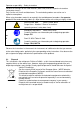
Operator responsibility – Safety instructions Observe all warnings for the used materials (bath fluids) and the respective instructions (safety data sheets). Only use the unit in well ventilated areas. The recirculating coolers are not for use in explosive atmosphere When using hazardous materials or materials that could become hazardous, the operator must affix the enclosed safety labels (1 + 2) to the front of the unit so they are highly visible: 1 Warning label W00: Colors: yellow, black Danger area.
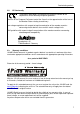
Recirculating coolers 2.2. EC Conformity The products described in the operating instructions conform to the requirements of the following European guidelines: Directive of the European Parliament and of the Council on the approximation of the laws of the Member States relating to machinery. Low voltage regulations with respect to legal harmonization of the member countries concerning electric devices for use within certain voltage limits.
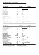
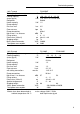
Operator responsibility – Safety instructions 2.4. Technical specifications (with T-pump) Working temperature range °C Cooling capacity (water-glycol) Refrigerant Heater capacity Pump capacity: Pressure max. Flow rate max.
Recirculating coolers (with T-pump) Working temperature range Cooling capacity (water-glycol) Refrigerant Heater capacity Pump capacity: Pressure max. Flow rate max. Pump connections Noise level, 1 m distance Filling volume Dimensions (WxLxH) Shipping weight Mains power connection Total power consumption °C °C kW kW bar Lpm dBA l cm kg V/Hz W (with S-pump) Working temperature range °C Cooling capacity °C (water-glycol) Refrigerant Heater capacity Pump capacity: Pressure max. Flow rate max.
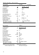
Operator responsibility – Safety instructions (with S-pump) Working temperature range Cooling capacity (water-glycol) Refrigerant Heater capacity Pump capacity: Pressure max. Flow rate max. with tubing connections Pump connections Noise level, 1 m distance Filling volume Dimensions (WxLxH) Ambient temperature Shipping weight Mains power connection Total power consumption (with Ju-pump) Working temperature range Cooling capacity (water-glycol) Refrigerant Heater capacity Pump capacity: Pressure max.
Recirculating coolers (with Ju-pump) Working temperature range Cooling capacity (water-glycol) Refrigerant Heater capacity Pump capacity: Pressure max. Flow rate max. with tubing connections Pump connections Noise level, 1 m distance Filling volume Dimensions (WxLxH) Ambient temperature Shipping weight Mains power connection Total power consumption (with Ju-pump) Working temperature range Cooling capacity (water-glycol) Refrigerant Heater capacity Pump capacity: Pressure max. Flow rate max.
Operator responsibility – Safety instructions Temperature selection digital (keypad) Resolution °C 0.1 MULTI-DISPLAY indications LED + LED Resolution °C 0.1 Display accuracy % 0.5 Temperature stability °C ±0.2 Temperature control on/off Control ratio for feed/return flow temperature, adjustable % 0 ...
Recirculating coolers 2.5. Cooling water connection Only for water cooled models - FCW: Cooling water pressure (IN / OUT ) max. 6 bar Difference pressure (IN - OUT ) 3.
Safety notes for the user 3. 3.1. Safety notes for the user Explanation of safety notes In addition to the safety warnings listed above, warnings are posted throughout the manual. These warnings are designated by an exclamation mark inside an equilateral triangle. “Warning of a dangerous situation (Attention! Please follow the documentation).” The danger is classified using a signal word. Read and follow these important instructions. Warning: Describes a possibly highly dangerous situation.
Recirculating coolers Do not drain the bath fluid while it is hot or cold! Check the temperature of the bath fluid prior to draining (by switching the unit on for a short moment for example). Use suitable connecting tubing. Avoid sharp bends in the tubing, and maintain a sufficient distance from surrounding walls. Make sure that the tubing is securely attached. Regularly check the tubing for material defects (e.g., for cracks). Never operate damaged or leaking equipment.
Operating controls and functional elements 4. 1. Operating controls and functional elements Mains power switch, illuminated 1. 11. 7. Filling funnel 8. Drain tubing 9. Drain tap 10. Filling level indication 11. Pump pressure gauge 7. 10. 8. 9. 2. MULTI-Display temperature indication 3. Indicator lights Alarm Heating Cooling 16 Temp.
Recirculating coolers 4. 5. 6. (LED 1) Keys for actual values A Key - Indication of feed temperature B Key - Indication of return temperature C Key - Indication of safety temperature 4.1 Key - Indication of actual temperature of external sensor 4.2 The "MENUE" key is not required for normal operating 4.3 The key "SPEC" is not required for this model version.
Operating controls and functional elements Rear 12.1 Pump connector: Feed 12.2 Pump connector: Return 13. Overflow port for bath tank 14. Connectors for solenoid valves 15. Mains power cable with plug 16.2 12.1 16.1 14. 12.2 ! 13. Only for water cooled models: 16.1 Cooling water OUTLET 16.
Recirculating coolers 5. Operation 5.1. Preparations 12.1 Place the unit in an upright position. The place of installation should be large enough and provide sufficient air ventilation to ensure the room does not warm up excessively because of the heat the instrument rejects to the environment. (Max. permissible ambient temperature: 40 °C). For a fault (leakage) in the refrigeration system, the standard EN 378 prescribes a certain room space to be available for each kg of refrigerant. > For 0.
Operation Notice: Cooling water circuit Risk of oil leaking from the cooling circuit (compressor) of the recirculating cooler into the cooling water in case of a fault in the circuit! Observe the laws and regulations of the water distribution company valid in the location where the unit is operated. 5.2. Return flow safety device Notice: Flood hazard!.
Recirculating coolers 5.3. Bath fluids Caution: No liability for use of other bath liquids! Please contact JULABO before using other than recommended bath fluids. JULABO takes no responsibility for damages caused by the selection of an unsuitable bath fluid Do not use alcohols. Water: The quality of water depends on local conditions. Due to the high concentration of lime, hard water is not suitable for temperature control because it leads to calcification in the bath.
Operation 5.5. Power connection Caution: Only connect the unit to a power socket with earthing contact (PE – protective earth)! We disclaim all liability for damage caused by incorrect line voltages! The power supply plug serves as safe disconnecting device from the line and must be always easily accessible. Never operate equipment with damaged mains power cables. Regularly check the mains power cables for material defects (e.g. for cracks).
Recirculating coolers 5.7. Draining Notice: Do not drain the bath fluid while it is hot or cold! Check the temperature of the bath fluid prior to draining (by switching the unit on for a short moment, for example). Store and dispose of the used bath fluid according to the environmental protection laws. Turn the mains switch (1.) off. Hold the venting grid, pull out and remove. 1. 33 22 44 Take the drain tubing (8.) out of the holder and hold it into a pail.
Operation 5.8. Connecting an external sensor Connect an external temperature sensor for measuring and controlling the temperature directly in the external system. (Control mode - see page 42). ACTUAL SET N 3 2 4 0 6 5 1 10. MAX MIN 9. Connect a Pt100 sensor (Order No. 8 981 003) or M+R Adapter with Pt100 sensor (Order No. 8 981 020) to connector "N" (sensor calibration - see page 42).
Recirculating coolers 6. Manual operation 6.1. Switching on Turn on the mains power switch (1.). An illuminated switch indicates the unit is on. ACTUAL 6.2. SET The unit performs a self-test. All segments of the 4-digit MULTI-DISPLAY (LED 1 + LED 2) and all indicator lights will illuminate. Then the model designation and software version appear on the MULTI-DISPLAY for about 3 seconds (Example: FC"1200", "n 9.0").
Manual operation 6.2.1. Automatic / non-automatic start mode NOTE: The recirculating cooler has been configured and supplied by JULABO according to N.A.M.U.R. recommendations. This means for the start mode, that the unit must enter a safe operating state after a power failure (non-automatic start mode). This safe operating state is indicated by „OFF“ or „rOFF“, resp. on the MULTI-DISPLAY (LED).
Recirculating coolers 6.3. Setting the setpoint temperatures Set the setpoints before or after starting the unit. Press the setpoint keys (E, F, G, H) to set a value and press the Enter key to store the value. The values will stay in memory when the recirculating cooler is powered down. 6.3.1. Setting the temperature Example: Setting the bath temperature Press the setpoint key ACTUAL SET . The indicator light blinks and the value previously set appears on the MULTI-DISPLAY (LED) (example: 10.8 °C)..
Manual operation 6.3.2. Setting the control ratio for feed/return flow temperature -0.5°C +0.5°C 50 50 20°C 21°C 22°C 50 (%) 0 100 20°C 22.5°C 21°C 0 .. 100 (%) In respect to the values for feed and return temperature and the factor set with the key "H" an almost constant temperature value may be maintained in the external system. The control function quickly responds to changing conditions (ambient temperature, reaction heat), and thus spares the use of an external sensor.
Recirculating coolers 6.3.3. Setting the safety temperatures This safety function is independent of the control circuit. Press the desired setpoint key (F, G). Follow the instructions under section 6.3.1. page 27 F G Recommendation: Set the high temperature limit at least 5 K above the actual bath temperature. Set the low temperature limit at least 5 K below the setpoint.
Manual operation 6.4. PID control parameters For internal and external control two separate parameter sets are available. The PID control parameters can be adapted to the requirements of the controlled member. The values are preserved after switching off the recirculating cooler. SET The control parameters are indicated by operating the key ACTUAL SET (5.1). Parameter Setting range CP 1 CP 2 CP 3 0.1 ... 100 K 1 ... 9999 s 0 ... 500 s Xp (example 4.0 K). Tn (example 160 s). Tv (example 20 s).
Recirculating coolers With the parameters HL (High Limit) and LL (Low Limit) the temperature of the internal bath is limited in case of external control. So, especially for big consumers, a great overshoot resp. undershoot of the internal temperature is avoided. Effect of the limitation of the internal bath temperature: Without limitation Limited internal temperature Each indicated control parameter can be optimized manually .
Manual operation Optimization instructions for the PID control parameters: The heat-up curve reveals inappropriate control settings optimum setting Inappropriate settings may produce the following heat-up curves: Xp too low Tv/Tn too low Xp or Tv too high 32
Recirculating coolers 7. Trouble shooting guide + ACTUAL SET Whenever the microprocessor electronics registers a failure, an alarm is triggered and a complete shutdown is performed. The alarm light illuminates and an audible signal is triggered. An error message appears on the MULTIDISPLAY (LED 2). Internal error High temperature alarm Low temperature alarm The values reported by the safety sensor and the sensor in the feed connector differ by more than 25 K (defective sensor).
Electrical connections 7.1. Other error messages ACTUAL Incorrect/invalid entry. Value too small or too large, or function not available. SET Under menu item E_Sb the parameter is set to 1, and the connection between Pin 2 and Pin 3 of the standby connector is interrupted (see page 36). 8. Electrical connections Notice: Use shielded cables only. The shield of the connecting cable is electrically connected to the plug housing.
Recirculating coolers 3 1 2 This potential-free change-over contact is activated in case of an alarm. Pins 2 and 3 are connected under the following conditions: - alarm - status "OFF" and "rOFF" - mains switch "off" Switching capacity max. 30 W / 40 VA Switching voltage max. 125 V/ Switching current max.
Electrical connections Stand-by input (L) Pin assignment: AK 1 3 2 Pin 1 2 3 Signal not used 5 V / DC 0V Activate the stand-by input: Under menu item E_Sb, set the parameter to 1 (see page 41). Connect an external contact 'AK' (e.g. for emergency switch-off) or an alarm contact of the superordinated application system.
Recirculating coolers 9. Remote control 9.1. Communication with a PC or data system ACTUAL SET For remote control, under the menu item OP (Operating mode) set the parameter to 1. The message "rOFF" appears on the display. In general, the computer (master) sends commands to the recirculating cooler (slave). The recirculating cooler sends data (including error messages) only when the computer asks for it.
Remote control Command Parameter Response of recirculating cooler out_sp_00 in_sp_00 xx.x no Set working temperature value Ask for working temperature value in_sp_01 no Ask for high temperature value in_sp_02 no Ask for low temperature value out_sp_03 xxx Set control ratio for feed/return flow temperature Ask for actual control ratio in_sp_03 no out_sp_07 in_sp_07 xx.xx xx.
Recirculating coolers 9.3. Status messages Message Description - Recirculating cooler ... 00 MANUAL STOP ... in condition "OFF" (LOCAL) 01 MANUAL START ... in keypad control mode (LOCAL) 02 REMOTE STOP ... in condition "rOFF" (RS 232) 04 REMOTE START ... in remote control mode (RS 232) 9.4.
Menu functions 10. Menu functions Set the parameters for the recirculating cooler via the configuration or calibration level. 10.1. Selecting/exiting the configuration level Simultaneously press the "MENUE" key (4.2) and + 1x 10.2. the edit key " " to select the configuration level or + 1x the edit key " " to exit the configuration level. + Select the menu items of the configuration level one by one by pressing simultaneously the menu key and one of the cursors.
Recirculating coolers 10.3.
Menu functions Attention: The following menu point Cont is only adjustable via the configuration level if the status is „OFF“. On a unit which is switched on this status is reached by switching on/off at the mains switch (1). ACTUAL 10.4. SET Cont - Control mode 0 = internal control 1 = external control (with an external sensor connected to "N") Selecting/exiting the calibration level Simultaneously press the "MENUE" key (4.2) and twice + 2x 10.5.
Recirculating coolers ACTUAL SET Ad¯P - Calibration of programmer input: Highest value = 80 °C ACTUAL SET AdP - Calibration of programmer input: Lowest value = -20 °C Calibration procedure: ACTUAL SET In the configuration level, set the programmer input type to allow control via an external programmer. 0 = Voltage 0 to 10 V 1 = Current 0 to 24 mA Connect an external programmer to the connector (O). Set the external programmer to the highest temperature value.
Menu functions Set the external programmer to the lowest temperature value. ACTUAL SET In the calibration level, select the item AdP and set the lowest temperature value (example: -20 °C). Press the setpoint key (E). Follow the instructions under section 6.3.1. page 27. Do not alter any setting on either of the units as long as the display "Ad_P" is blinking.
Recirculating coolers 11. Cleaning / repairing the unit Caution: Always turn off the unit and disconnect the mains cable from the power source before cleaning the unit. Prevent humidity from entering into the circulator. Service and repair work may be performed only by authorized electricians. In order to maintain a good condition of the cooling compressor, the condenser should be checked for contamination in regular intervals. 3 2 4 0 6 5 1 Switch the unit off, disconnect the power plug.