
Data Sheet

9
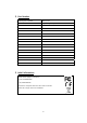
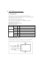
8. BOOT MODE(download firmware).
8-1. Boot Mode Pins
The Module has a boot mode to program the internal flash memory.
Boot mode will be activated by setting BOOT pin to “Low” level at reset timing.
(Normal operation mode is “High” level)
Boot mode supports either UART boot or SPI boot.
UART booting uses the TXD10/RXD10 ports, and SPI booting uses the
MOSI10/MISO10/SCK10/SS10 ports.
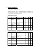
The following pins are used in boot mode.
Table : Boot mode pin list
Block Pin Name Dir Description
SYSTEM nRESET I Reset Input signal
BOOT/PB3 I ‘0’ to enter Boot mode
UART mode of
USART10
RXD10/PB1 I UART Boot Receive Data
TXD10/PB0 O UART Boot Transmit Data
SPI mode of
USART10
SS10/PB3 I SPI Boot Slave Selectable after Boot ROM
SCK10/PB2 I SPI Boot Clock Input
MISO10/PB1 I SPI Boot Data Input with function exchange
MOSI10/PB0 O SPI Boot Data Output with function exchange
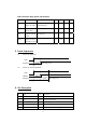
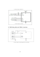
8-2. Boot Mode Connections
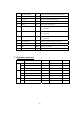
User can design target board using any of boot mode ports – UART or SPI mode of USART10.
The following diagrams are some examples of connection diagrams in the boot mode.