
Installation Guide


List of Figures
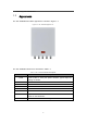
Figure 1-1 JRL-113BT48 Appearance .......................................................................... 2
Figure 2-1 Weatherproofing ......................................................................................... 8
Figure 3-1 Installation Process ..................................................................................... 9
Figure 3-2 GPS Antenna Installation ............................................................................ 9
Figure 3-3 Power Core Connection Relation ............................................................. 14
Figure 3-4 Grounding Screws .................................................................................... 15
List of Tables
Table 1-1 JRL-113BT48 Interface Description ............................................................. 2
Table 1-2 JRL-113BT48 LED Indicators ....................................................................... 3
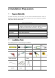
Table 2-1 Support Materials ......................................................................................... 6
Table 2-2 Environmental Requirements ....................................................................... 7