
Operation Manual


● ● ● ● ● ● ● ● ● ● ● ● ● ● ● ● ● ● ● ● ● ● ● ● ● ● ● ● ● ● ● ● ● ● ● ● ● ● ●
3-91
3
Checking procedure
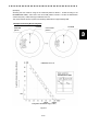
① Read a current value A on the bar indicator.
② Referring to the Calibration Curve I, obtain a relative attenuation d(B) for the initial bar
indicator length B that is specified in the INFORMATION LABEL.
③ Then, obtain a relative attenuation d(A) for the value A referring to the Calibration Curve I.
The value given by d(A) - d(B) represents the attenuation of the current transmission
output power compared with the value at the initial time.
④ If the attenuation value given by d(A) - d(B) is 10 dB or more (due to the life of the
magnetron), it is necessary to request for checking of the transmitter system by a service
engineer.
Figure 1
Initial bar
length
Calibration Curve I
Relative Attenuation d
Length of Bar Indicator l
Date and time o
f
initial setting
Measurement precision
Maximum range
pattern