
Operation Manual


● ● ● ● ● ● ● ● ● ● ● ● ● ● ● ● ● ● ● ● ● ● ● ● ● ● ● ● ● ● ● ● ● ● ● ● ● ● ●
1−23
1
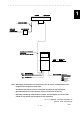
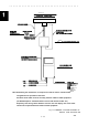
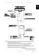
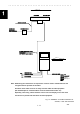
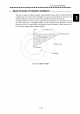
NKE-1089-7 SCANNER UNIT
SK-32C
(5A)
GYRO
LOG
GPS
250V-MPYCYS-5
250V-DPYCYS-1.25
250V-TTYCS-1
660V-TPYCYS-5.5
NCD-4263 DISPAY UNIT
SHIP'S MAIN
AC100/110/220/230V
60Hz, 1φ
AC220/230V
60Hz, 3φ
600VA
NTG-3028 TRANSMITTER-RECEIVER UNIT
14 CORES COMPOSITE CABLE
FLEXIBLE WAVE GUIDE
14 CORES COMPOSITE CABLE
CIRCUT BREAKER
(OPTION)
H-2695110056
MAX 35MT φ23 (JRC SAPPLY)
H-2695110056
MAX 30MT φ23 (JRC SAPPLY)
250V-DPYCYS-1.25
SHIP'S MAIN
AC100/110V
50/60Hz, 1φ, 100W
FR-9 (JRC SAPPLY)
Eliminating the interference on frequencies used for marine communications and
navigation due to operation of the radar.
All cables of the radar are to be run away from the cables of radio equipment.
(Ex. Radiotelephone. Communications receiver and direction finder. etc)
Especially inter-wiring cables between scanner unit and display unit of the radar
should not run parallel with the cables of radio equipment.
Note:
Fig.1.15 GENERAL SYSTEM DIAGRAM OF
RADAR, TYPE
JMA-9923-7XA
9923
4 2 6 3
- 1 0 8 9 - 7
3028
AC100/230V
50/60Hz, 1
AC230V
50/60Hz, 3
800VA
Φ
Φ
Φ