
Operation Manual


● ● ● ● ● ● ● ● ● ● ● ● ● ● ● ● ● ● ● ● ● ● ● ● ● ● ● ● ● ● ● ● ● ● ● ● ● ● ●
A-19
APPENDIX
1-2 Initial Setting
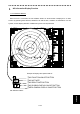
■GPS Antenna installation position Setting
The distance of the GSP antenna from the position of the radar scanner should be set.
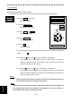
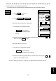
1. Left-click MENU on the screen.
MAIN menu opens.
2. Left-click CODE INPUT.
CODE INPUT menu opens.
3. Left-click 0 → END .
ADJUST menu opens.
4. Left-click ARPA/AIS .
ARPA/AIS menu opens.
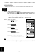
5. Left-click AIS .
AIS menu opens.
6. The GPS antenna rough direction from the radar scanner is chosen with the GPS
button “ . “.
7. Left-click the button in the a:
box of "1.GPS ANT.LOCATION".
The distance of the GPS antenna from the radar scanner in bow-stern
direction should be entered. (The direction of the bow side is plus and the
direction of the stern side is minus.)
8. Left-click the button in the b:
box of "1.GPS ANT.LOCATION".
The distance of the GPS antenna from the radar scanner in port-starboard
direction should be entered. (The direction of starboard side is plus and the
direction of the port side is minus.
Note1
Unless it performs this setup correctly, the position of an AIS symbol may not
coincide with the radar echo position of the target.
Note 2
When this setup is performed, offset is added to the data received from GPS, and
the compensated latitude and longitude are displayed as own ship position. It
would be the radar scanner installation position.
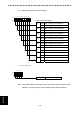
Operation
procedure
ADJUST
ARPA/AIS
AIS
1.GSP ANT. LOCATION
a: + 100
b: + 100
(-500 to +500[m])
0. EXIT
a
b