
Operation Manual


● ● ● ● ● ● ● ● ● ● ● ● ● ● ● ● ● ● ● ● ● ● ● ● ● ● ● ● ● ● ● ● ● ● ● ● ● ● ●
A-1
APPENDIX
1. GENERAL
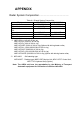
1.1 Outline・・・・・・・・・・・・・・・・・・・・・・・・・・・・・・・・・・・・・・・・・・・・・
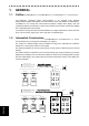
The NQE-3141 interswitch allows interconnections to be changed freely between
bridge-installed multiple radar display units and multiple scanner units different in characteristics.
The NQE-3141 can change the interconnections between multiple radar display units and
multiple transmitter-receiver/scanner units (in the remainder of this manual, referred to as MTRs)
in the JMA-9900 Series radar system.
It is possible to change the interconnections between up to eight combinations of units: (two units
in the case of a built-in type) x (four units in the case of a separate type).
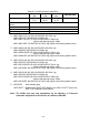
1.2 Interswitch Construction・・・・・・・・・・・・・・・・・・・・・・・・・・・・・
The Interswitch Kit is incorporated in the display unit. (Option)
The number of combined display units and MTRs according to the interswitch kit is different
between the 2-units system and the 3-units system.
The distinction between the 2-units system and the 3-units system is determined by the internal
settings.
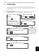
The pattern switchover operations can be exercised simply and quickly according to the menus
displayed on the display unit. The interseitch patterns as shown below are displayed at the upper
left of the radar display. (The position filled on the mark indicates the position of the display unit
currently operated.)
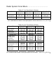
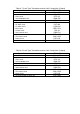
Radar system of
2-radar indicators
......
Interswitch patterns
(Combinations of six patterns)
Unit arrangement (towards the ship's heading)
MTR (L)
MTR (R)
Display unit (L) Display unt (R)
Display unit
MTR
L R
L R
No.1 No.2
No.3 No.4
No.5 No.6
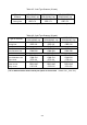
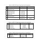
Radar system of
3-radar indicators
......
Interswitch patterns
(Combinations of twelve patterns)
Unit arrangement (towards the ship's headhing)
MTR (L)
MTR (R)
Display unit (L)
Display unit (R)
MTR (C)
Display unit (C)
Display unit
MTR L C R
L C R
No.1 No.2
No.3 No.4
No.5 No.6
No.7 No.8
No.9 No.10
No.11
No.12