
Operation Manual


● ● ● ● ● ● ● ● ● ● ● ● ● ● ● ● ● ● ● ● ● ● ● ● ● ● ● ● ● ● ● ● ● ● ● ● ● ● ●
8-41
8
90×
OFF ON
180×
ON OFF
360×
OFF OFF
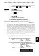
S1-4・・・・・・・・・・・・・・・・・・ Gyration direction
「ON」・・・・・・・・・ Reverse (counterclockwise)
「OFF」・・・・・・・・ Normal (clockwise)
• S1-5-8: Set this switch assembly according to the particular type of log.
S1-5・・・・・・・・・・・・・・・・・・ Log type-1
「ON」・・・・・・・・・ Synchro signal
「OFF」・・・・・・・・ Pulse signal
S1-6・・・・・・・・・・・・・・・・・・ Log type-2
「ON」・・・・・・・・・ 1-axis
「OFF」・・・・・・・・ 2-axis
S1-7,8・・・・・・・・・・・・・・・・ Log ratio
Log ratio S1-7 S1-8
100P/30×
ON ON
200P/90×
OFF ON
400P/180×
ON OFF
800P/360×
OFF OFF
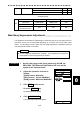
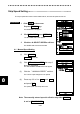
②
Connect the gyro signal and the log signal cables to the Terminal Board Circuit.
③
Set S7 to [ON].
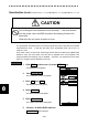
After power-on operation, the switch S1-4 shall be set to [ON] if the radar video and
the indicated value of COPURSE (own ship’s true bearing) is reversed.
Table 8.14 Gyro and Log Select Switches (S1 Dip Switch)
S1 Setting Table
S1
1 2 3 4 5 6 7 8
STEP TYPE ON
SYNC TYPE OFF
36×
ON ON
90×
OFF ON
180×
ON OFF
RATIO
360×
ON OFF
REV (Reverse) ON
GYRO
SIG.
/
GYRO
SIGNAL
SET
DIRECTION
NORM (Normal) OFF
SYNC ON
TYPE1
PULSE OFF
1AXIS
ON
TYPE2
2AXIS
OFF
LOG SIG.
/
LOG
SIGNAL
SET
PULSE
100P/30×
ON ON