
User Manual

9303 Programming Examples 4
7- 8-CHANNEL SETUP
2 Aileron Channels, 2 Elevator Channels, 2 Rudder Channels, Optional D/R Switch(s)/Flight Modes,
Optional Retracts
This example identifies the steps necessary to program an 7- 8-channel setup where the ailerons are
controlled by 2 separate channels, Elevators are controlled by 2 channels, Rudder is controlled by 2
channels, Dual Rates/Exponential curves are controlled either by individual switches for Aileron,
Elevator and Rudder, or via a single Flight Mode switch. It may optionally be equipped with retractable
landing gear as the 7
th
or 8
th
channel.
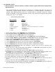
RECEIVER CONNECTIONS
RX CHANNEL SERVO
1 Throttle Throttle
2 Aileron Right Aileron
3 Elevator Right Elevator
4 Rudder Right Rudder Servo
5 Gear (if equipped) Retract (or 2 retract servos connected via "Y" harness)
6 Flap (AUX1) Left Aileron
7 AUX2 Left Rudder Servo
8 AUX3 Left Elevator
1. Select a Model Memory using Model SEL in the SYSTEM Menu.
2. Reset the Model Memory using MDL Reset in the SYSTEM Menu.
3. Enter a Model Name using MDL Name in the SYSTEM Menu.
4. Set the Modulation Type to match the receiver using MODULAT in the SYSTEM Menu.
5. Inhibit the Flap TRIM and the Flap channel in the Devic.SEL function of the SYSTEM Menu.
6. Inhibit AUX2 in the Devic.SEL function to make it available for a 2
nd
Rudder channel.
7. Inhibit AUX3 in Devic.SEL to make it available for a 2
nd
Elevator channel.
8. Access Wing Type in the Function List and set the wing type to FLAPERON.
9. Access Wing Type in the Function List and assign AUX2 as a Dual Rudder channel.
10. Access Wing Type in the Function List and assign AUX3 as a Dual Elevator channel.
11. Plug servos into the RX and check servo directions. Reverse servos as may be necessary using
REV.SW in the Function List.
12. Install servo arms so they are 90 degrees to their linkages. Use Sub Trim in the Function List to fine-
tune the arms so they are 90 degrees to the linkages.
13. Adjust travel of each servo in both directions using TRVL ADJ. In the Function List.
14. If Dual Rates are to be combined on 1 switch or there is a need to group other functions together, access
Devic.SEL and activate Flight Modes. Also set Dual Rates to FM in the same function.
15. Set up Dual Rate and Exponential curves using D/R & EXP in the Function List.
16. If throttle response is not linear, set up a throttle curve using THRO CURV in the Function List.
17. If Aileron Differential is required, access AIL DIFF. In the Function List and set values.
18. If Elevator to Flap mixing is desired for tight loops, access ELEÆFLP M in the Function List and set
throws.
14. Set up a count down timer using TIMER to help prevent running out of fuel while flying.
15.
After test flying and fine-tuning the programming, use COPY in the Model SEL function contained in
the SYSTEM Menu to make a backup copy of the program.