
User Manual


FAIL SAFE
Fail Safe is available only when SPCM has been selected as the Modulation Type in the
SYSTEM Menu. Obviously, the receiver must be of the PCM variety, as Fail Safe does not
function in the PPM/FM mode. Fail Safe will appear in the FUNCTION List only if SPCM has
been selected as the modulation type in the MODULAT function of SYSTEM Menu.
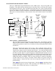
When interference occurs on the frequency of operation, PCM receivers do not pass the
interference on to the servos. Instead, the receiver commands the servos to either hold their last
good position (HOLD) or to move to a pre-determined position (Fail Safe – F.S.). Both options
exist for each channel/servo and the settings are adjustable in the Fail Safe function.
Many experienced pilots designate all channels as HOLD, except for the throttle – it is
commanded to assume a Fail Safe position that corresponds to idle. In this configuration the
aircraft will continue to do whatever it was doing before the interference occurred, except the
throttle will reduce to idle. The servos will continue to hold their last position and the throttle
will remain at idle until the interference subsides, at which time normal operation is resumed.
More often than not, the pilot will not realize the system went into failsafe except for hearing the
throttle momentarily reduce RPM. This is also a good configuration if interference is
encountered while the aircraft is on the ground because the throttle returns to idle, reducing the
chances of the aircraft careening out of control at a higher throttle setting. In the event that the
interference does not subside and the system remains in Fail Safe, it is better for the aircraft to
crash with the engine at idle than at a higher throttle setting.
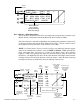
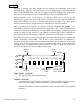
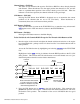
[Fail Safe]
Function
Name
THR AIL ELE RUD GER FLP A2X2 AX3
F.S.
HOLD
Model 15
Channels
Model
Number
AX4=HOLD
AUX4 always =
HOLD
Legend
Channel Status
F.S. or HOLD
ENT
LIST
CLR
Model Number – (Fail Safe)
This is the presently selected model memory.
Channels – (Fail Safe)
8 of the channels are presented in a row and the 9
th
channel (AX4) is shown in the lower
right corner of the display. The AUX4 channel is always designated as HOLD.
Channels are renamed to represent assignments made in the Devic.SEL and Wing TYPE
functions.
JR XP9303 Detailed Function Descriptions 88