
User Manual
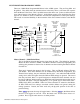


Curve/Line – (Multi-Point Mixer)
The Curve/Line is the line that results from connecting all of the points together based
upon their point values. The default curve is a straight line that is on a 45-degree angle.
This configuration is said to be Linear because there is an equal and constant relationship
between the Master channel position and servo movement. When the master channel
moves 10% of its travel, the slave channel moves 10% of its travel.
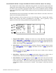
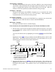
Graph – (Multi-Point Mixer)
The graph illustrates the mixing curve. The X-Axis (horizontal plane) represents Master
channel movement. The Y-Axis (vertical plane) represents the Slave servo movement
where the bottom ½ of the graph is one direction from neutral and the top portion of the
graph is the other direction.
Points That Can Be Adjusted – (Multi-Point Mixer)
The points that can be adjusted are listed vertically by name and are also displayed by
number along the bottom of the graph. Use the numbers along the bottom of the graph to
determine which point(s) need adjustment.
Change the value of a point by highlighting and selecting the Point Name and dialing-in
the desired percentage.
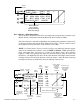
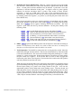
Exponential – (Multi-Point Mixer)
This parameter smoothes the Curve/Line between all of the points on the graph to provide
a smoother mixing response. The default value is OFF. To turn it on and smooth the
mixing curve, highlight and select OFF and it will toggle to ON.
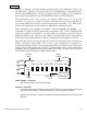
Slave Channel Position – (Multi-Point Mixer)
The Slave servo position next to OUT at the bottom left of the display is expressed in
values from –100 to +100, with 0 being neutral or center. It represents the servo travel
that corresponds to the present Master Channel position.
Note: When the mixer is switched OFF, the out value will change to OFF instead of
displaying the Slave position. This is how to determine if the mixer is ON or OFF.
Master Channel Position – (Multi-Point Mixer)
The Master channel position is shown on the bottom line of the display next to IN and is
expressed in values from 0 to 100 with 50 being the center or neutral position. It
represents the present Master channel position.
Select Switch – (Multi-Point Mixer)
There are 4 switches that can always be used to turn the mixer On and Off. They include
the Aileron D/R switch, Gear Switch, Rudder D/R switch and the Mix switch. In
addition, if Flight Modes are activated in the Devic.SEL function, then 3 more switch
positions may be selected FM0, FM1, and FM2, which correspond to the 3 positions of
the Flight Mode switch.
To select a switch to turn the mixer On and Off, highlight and select SW SELECT to
obtain a list of available switches and select the desired switch.
Note: When the mixer is turned off, OFF will appear next to OUT at the bottom of the
display where the Slave position is normally displayed. This is how to determine if the
mixer is ON or OFF.
JR XP9303 Detailed Function Descriptions 84