
User Manual

[GYRO SYS. ]
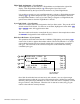
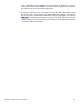
Function
Name
AUX2: AX2 SW
STICK INH
Stick
Override
Status.
Replaced
by Stick
Name when
A
ctive
CEN 0: 0% FM0: S
1: 50% FM1: S
2: 90% FM2: S
Gyro Gain
Switch. Can
be AX2 SW
or FLP SW.
Gyro Gain for each switch position when Stick
Override is Inhibited. When Stick Override is Active,
this is the Gyro Gain when the stick is at Center.
A
UX2 Settings.
If AUX3 is
designated for
GYRO in
Devic.SEL,
then all of this
data is
repeated below
for AUX3
ENT
LIST
CLR
A
UX Channel
Controlling
Gyro Gain
Flight Mode
A
ssignments. Can
be S, 0, 1, 2,
corresponding with
Gyro switch, Pos-0,
1, 2 Gain values.
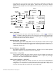
Gyro Gain – (Gyro System)
When Fixed Gyro Gain is used, these values are the 3 gain values that are available using
the Gyro Gain switch or Flight Mode switch. When a gain is selected with a switch, it
remains constant regardless of stick movement.
The 3 Gyro Gain values correspond to the positions of a 3-position switch where 0
represents the switch being in the upper position; 1 represents the middle position; and 2
represents the lower position.
When Stick Override is activated, these values represent the gyro gain when the stick is
in its Center position.
It is a good idea to leave the first gain value set to 0% as it provides the ability to turn the
gyro OFF. This can be handy if a gyro becomes overly sensitive while in flight.
AUX2 Settings – (Gyro System)
The sample display above illustrates the parameters for AUX2 when AUX2 has been
designated as a Gyro channel in the Devic.SEL function.. The same parameters exist for
AUX3 when the AUX3 channel is designated as GYRO in the Devic.SEL function.
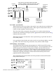
When AUX3 has been designated as a Gyro channel, the same parameters appear in the
bottom of the display as is shown for AUX2. If Only AUX3 is designated as a Gyro
channel, the top portion of the display will be blank and the bottom portion will be
populated with the AUX3 parameters.
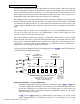
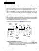
The example below shows both AUX2 and AUX3 parameters and the AUX2 Switch
being used for both Gyros.
[GYRO SYS. ]
AUX2: AX2 SW
STICK INH
AUX3: AX2 SW
STICK INH
CEN 0: 0% FM0: S
1: 50% FM1: S
2: 90% FM2: S
1: 50% FM1: S
CEN 0: 0% FM0: S
2: 90% FM2: S
ENT
LIST
CLR
JR XP9303 Detailed Function Descriptions 64