ACRO – DETAILED FUNCTION DESCRIPTIONS This section contains detailed descriptions of the information presented on the Main Display as well as the functions contained in the SYSTEM Menu and FUNCTION List. It is to be used as a supplement to the general descriptions found in the main portion of the XP9303 manual. The functions are presented in the same order as they appear in the SYSTEM Menu and FUNCTION List.
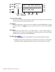
Integrated Timer The Integrated Timer is shown under the model name. It indicates the total TX on-time for the current model. It can be reset in the Timer function found in the FUNCTION List. Display Contrast Adjust The Display Contrast Adjust parameter can be selected and adjusted on the Main Display. Use the rotary selector to highlight and select this parameter and adjust the display contrast for best viewing. The contrast may require adjustment for extreme changes in temperature.
SYSTEM Menu The SYSTEM Menu is obtained by holding down the ENT button while switching the transmitter (TX) on. The functions contained in this menu are listed below followed by detailed explanations of each function. ENT LIST CLR [SYSTEM M.] INFO-DISP TRANSFER Model SEL TRIM STEP MDL Name Devic. SEL Wing Type Type SEL MDL Reset MODULAT INFO-DISP – Information Display (Main Display) Selecting the INFO-DISP parameter exits in the SYSTEM Menu and displays the Main Menu.
TRANSFER – Transfer a Model to Another XP9303 TX or to a DataSafe Unit Selecting the TRANSFER function initiates the Transfer display. This function is used to transfer the contents of the current model memory to another XP9303 transmitter or to a DataSafe unit attached to a personal computer (PC). It is also used to transfer data TO the 9303 from another 9303 TX or DataSafe unit. TRIM STEP – Trim Step or Trim Resolution Selecting the TRIM STEP function brings up the Trim Step display.
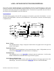
Model SEL – Model Select The first thing to do when setting up a new model is to select a model memory for it. It is best to select an unused model memory, however, a memory that already contains data for another model may be used so long as data for that model is no longer required because any data in that memory will be lost. This function is also used to select a model that is to be flown after programming for the model is complete.
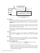
ENT [Model SEL] Select LIST MODEL 15 CLR Currently Selected Model MODEL 13 ACRO MODEL 14 ACRO MODEL 15 ACRO MODEL 16 ACRO MODEL 17 ACRO Model Memory # Select to Select Different Model SPCM GWS Corsair SPCM H9 Ultimate Bipe SPCM H9 EXTRA 330S SPCM SPCM Model Modulation Type Type Use Rotary Selector to Scroll Up and Down in List and Select Desired Model Model Name Currently Selected Model Shows the model memory that is currently selected in the event that one loses track while scrolling up and down
COPY – Model Select The Copy function is part of the Model SEL function described above and allows the contents of the current model memory to be copied into another model memory in the same transmitter. It is not used to transfer the model to another transmitter or to a DataSafe unit – the TRANSFER function provides for these activities. The Copy function is very valuable because it can provide some insurance against losing programs (aircraft setups) that may have been time consuming to create.
make sure to use an unused model memory or a memory that contains an aircraft setup that is no longer required. Select a model memory that is to receive the copy by highlighting and selecting the model memory number, scrolling to the desired model and selecting it with the rotary selector. Function Name ENT Copy Function.
3. Verify that the top model is the model that is to be backed-up and the lower model is empty or contains a model that is no longer required. When satisfied that all is well, press the CLR button on the left side of the display next to COPY. The entire contents of the currently selected model is copied to the lower model on the display and there is now a complete backup of the current model.
Cursor – shows where next letter will be inserted in model name. Move it with the rotary selector. Then press rotary to obtain character list. Function Name ENT [MDL Name] LIST MODEL 15 ACRO < EXTRA 3 > SPCM !”#$%&‘()*+,-./01234567 CLR 89:;<=>?@ABCDEFGHIJKLMNO PQRSTUVWXYZ [¥]^_ abcdefg hIj KLMNOPQRSTUVWXYZ { | }~ Next Character to be inserted into Model Name. Highlight with rotary selector and press rotary to insert character into name.
Type SEL – Model Type Selection Part of setting up each model involves indicating the type of aircraft. The XP9303 supports Sailplanes (GLID), Powered Fixed-Wing Aircraft (ACRO) and Helicopters (HELI). The Type SEL function is obtained by selecting Type SEL from the SYSTEM Menu. Use the rotary selector to highlight and select the appropriate model type.
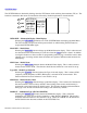
MDL Reset – Model Reset The Model Reset function is used to return all of the data to the factory defaults for the currently selected model. When setting up a new model it is important to reset all parameters to their default or factory settings before proceeding with any other programming. This is to ensure that there are no program mixes, trims or other "surprises" left over from a previous model or programming session. The Reset function is obtained by selecting MDL Reset in the SYSTEM Menu.
Function Name ENT [MDL Reset] LIST LST CLR NO MODEL 15 ACRO SPCM EXTRA 300S Are you sure? YES Press the button next to YES to Continue with the Reset operation Press the NO button next to RES/CLR to Cancel the Reset operation Message Flashes while waiting for an answer (YES/NO) TO RESET A MODEL MEMORY 1. In the SYSTEM Menu, highlight and select MDL Reset using the rotary selector. 2. Press the CLR button that is next to RES on the display. 3.
Modulation Select this parameter with the rotary selector to change the modulation type. Function Name ENT [MODULAT.] LIST MODEL 15 ACRO EXTRA 300S Modulation CLR SPCM PPM Choose a Modulation Type to match the Receiver Modulation Selector. Select to change Modulation Type LIST Button Press the LIST button to return to the list of functions in the SYSTEM Menu, or rotate the rotary selector until LST appears next to LIST and select it to return to the SYSTEM Menu.
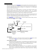
TRANSFER – Transfer a Model Memory To/From another XP9303 or DataSafe Unit The TRANSFER function is used to copy the contents of a model memory to another XP9303 transmitter or to a DataSafe unit connected to a Personal Computer (PC). It is also used to receive data for a model either from another XP9303 transmitter or from a DataSafe unit. To obtain the Transfer function, select TRANSFER from the SYSTEM Menu.
TRANSMIT indicates the XP9303 is to transmit the model to another XP9303 or DataSafe.
TO TRANSFER A MODEL FROM THE XP9303 1. Hold the ENT button while plugging the DSC cord into the back of the transmitter to obtain the SYSTEM Menu. Plug the other end of the DSC cord into another XP9303 transmitter while holding the ENT button down and prepare that transmitter for Receive as described in the next subsection below. Or, plug the other end of the DSC cord into a DataSafe unit and prepare the DataSafe for Receive. Highlight and select TRANSFER in the SYSTEM Menu to obtain the Transfer display.
Current Model Memory This is the currently selected model memory. The data for this model will be completely replaced by the data received from another XP9303 transmitter or from a DataSafe unit. The model memory should be unused or contain data for a model that is no longer required because the data will be lost when the new data is received. To change the model memory that is to receive the data, highlight and select the model memory using the rotary selector and scroll to an unused model.
Function Name ENT LIST CLR RECEIVE indicates the XP9303 is to Receive the model from another XP9303 or DataSafe. Select this parameter to toggle between Transmit and Receive [TRANSFER] RECEIVE START START – Press the button next to START/CLR to begin Receiving the model data. Current Model MODEL 15 MODEL 14 SPCM MODEL 15 ACRO SPCM EXTRA 300S MODEL 16 SPCM Current Model Memory that is to Receive the model from another XP9303 or DataSafe.
Plug the other end of the DSC cord into another XP9303 transmitter while holding the ENT button and prepare that transmitter for Transmit as described above. Or, plug the other end of the DSC cord into a DataSafe unit and prepare the DataSafe for Transmit. 2. Highlight and select TRANSFER in the SYSTEM Menu to obtain the Transfer display. 3. If RECEIVE is already displayed, continue with the next step. If TRANSMIT is displayed, highlight and select TRANSMIT, changing it to RECEIVE. 4.
NOTE: When adjusting the analog throttle trim, the total trim travel is actually reduced when set to less than 100%. Use a fairly coarse setting such as 4-6 when test flying an aircraft in order to trim the aircraft quickly and then use a finer setting such as 3-1 for final precision trimming. Enter the Trim Step function by selecting TRIM STEP from the SYSTEM Menu.
ACRO - SYSTEM MENU - ADVANCED FUNCTIONS There are two functions in the SYSTEM Menu that govern some of the more advanced features of the XP9303 system. They are the Devic. SEL and Wing Type functions. The Devic. SEL function is used to activate and inhibit Flight Modes; change switch assignments; Activate and Inhibit the Flap and Gyro Systems; Activate and Inhibit switches/channels and to Activate/Inhibit the FLAP TRIM lever that is next to the FLAP switch on the TX.
Switch/Lever Status The status of each switch is shown on the OUT line at the bottom of the display. A switch/lever can be Active (ACT) where the switch controls the channel, or Inhibited (INH) where the switch does not control the channel, making the switch available for other purposes. In the case of the FLAP channel, the switch can also be set to System (SYS), indicating that the Flap System will be active and controlled by the switch.
switch). The pilot decides which switch is to be used when Flight Modes are activated in the Devic.SEL function in the SYSTEM Menu. Once Flight Modes are activated the pilot has a choice of using the Flight Mode switch to select up to 3 Dual Rates and Exponential settings for each of the primary controls (ELEV, AILE, RUDD) or Dual Rates and Exponential settings may continue to be controlled by the 3 individual Dual Rate switches.
TO ACTIVATE FLIGHT MODES 1. From the SYSTEM Menu highlight and select Devic. SEL using the rotary selector. Function Name ENT LIST [Devic.SEL] FLIGHT MODE INH Remainder of display omitted for clarity CLR Flight Mode Status. Highlight and select to activate Flight Modes 2. Using the rotary selector, highlight and select INH under FLIGHT MODE. When selected, two options appear: AUX2 SW and FLAP SW. Highlight and select the switch that will be used to select between Flight Modes while flying.
TRIM:COM – (Flight Modes) The TRIM:COM parameter can be toggled back and forth between COM and FM by pressing the rotary selector when COM or FM is highlighted. If left in the COM mode, the digital trims for elevator, ailerons, and rudder are Common or shared by the 3 Flight Modes. If FM is selected the XP9303 keeps track of the digital trims independently for each Flight Mode which means the pilot can re-trim the aircraft using the digital trims for each Flight Mode.
D/R:SW – (Flight Modes) The D/R:SW parameter may be toggled between SW and FM by pressing the rotary selector when SW or FM is highlighted. If left in the SW mode then the 3 separate Dual Rate switches will be used to select Dual Rates and Exponential settings for elevator, ailerons, and rudder and there will only be 2 sets of Dual Rates/Expo settings for each control.
SWITCH ASSIGNMENTS – Devic.SEL The XP9303 Provides the ability to change the standard default switch assignments for GEAR, FLAP, AUX2, AUX3, AND AUX4. Changing the assignments may be a matter of preference or to help overcome a disability in one hand. In any event, the standard switch assignments may be changed in Devic.SEL function contained in the SYSTEM Menu. To obtain the Switch Assignment display, highlight and select Devic.SEL in the SYSTEM Menu. Function Name ENT LIST CLR [Devic.
TO CHANGE A SWITCH ASSIGNMENT 1. From within the Devic.SEL function use the rotary selector to highlight and select GEAR, FLAP, AUX2, AUX3, or AUX4 along the top line of the display. 2. Once a switch is selected a list of available replacement switches is displayed. Highlight and select the desired switch with the rotary selector. 3. Repeat for as many switches as desired FLAP TRIM ON/OFF – Devic.SEL The digital FLAP TRIM lever is located next to the FLAP switch.
ACTIVATE/INHIBIT SWITCHES – Devic.SEL The XP9303 provides the ability to disable a number of the switches and levers – GEAR, FLAP, AUX2, AUX3, and AUX4. This is very useful when auxiliary channels are used as Dual primary flight controls such as using 2 channels/servos for 2 elevator halves and/or using 2 servos/channels to operate the rudder.
Possible Values for Each Switch The GEAR and AUX4 switches may have a value of ACT or INH. If set to ACT the switch is active and will control the channel. If set to INH, the switch is not active and will not control the channel. The FLAP channel may be set to ACT, INH or SYS. If set to ACT the switch is active and will control the channel. If set to INH, the switch is not active and will not control the channel. If set to SYS.
Wing TYPE – Wing Type (Wing Configuration, V-tail, Dual Primary Channels, Twin Engine) The Wing Type function provides for 3 different wing types (NORMAL, FLAPERON, and DELTA). NORMAL is used when the Aileron channel is the only channel to be used to control ailerons, either with 1 servo, or 2 servos connected through a Y-harness to the aileron channel. It is also used when the aircraft is equipped with flaps that are separate from the ailerons.
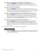
Wing – Wing Configuration – Normal, Flaperon, Delta The Wing parameter allows selection of the aircraft's wing type: Normal, Flaperon or Delta. Function Name ENT LIST CLR Wing TYPE. Select Wing and then select the wing TYPE – NORMAL, FLAPERON, or DELTA [Wing TYPE] Wing: NORMAL V-tail: INH NORMAL FLAPERON DELTA Dual AILE ELEV RUDD FLAP Mate INH INH INH INH Trim - TWIN E.
V-tail – (Wing Type) If the aircraft has a V-tail configuration, highlight INH next to V-tail in the Wing TYPE function and press the rotary selector until ACT appears. Plug the Right Elevator servo into the Elevator channel (Ch.3) and plug the Left Elevator servo into the Rudder channel (Ch.4). Pressing the rotary selector toggles the parameter between ACT & and INH.
Function Name ENT LIST CLR [Wing TYPE] Wing: FLAPERON V-tail: INH TWIN E. Dual AILE ELEV Mate INH INH Trim - RUDD FLAP MATE INH INH INH GEAR AUX2 Trim - AUX3- - - AUXT INH - Channels must be INHIBITED in Devic.SEL before they will appear in the list as available for Dual channel use. Channels Available to use as nd a 2 Rudder Channel. Select one Trim The Trim line at the bottom of the display is used to Activate/Inhibit the special trims associated with the FLAP and AUX3 channels.
Twin E. – Twin Engine Throttles (Wing Type) If the aircraft is equipped with twin engines the Twin Engine feature (Twin E) may be used for a 2nd throttle channel with an optional separate digital trim and throttle curves. The FLAP or AUX3 channel must be selected as the Mate for the additional trim to be available.
Select the FLAP or AUX3 channel as the Mate if a separate trim lever is desired for the 2nd throttle channel. Any channel in the list may be selected if an additional trim is not desired. The normal throttle trim can trim both channels at the same time. Plug the 2nd throttle servo into the channel selected as the Mate. Trim Trim must be set to ACT if the 2nd throttle channel is to be trimmed either with the normal throttle trim or with a special trim (FLAP Trim or AUX Trim).
ACRO – FUNCTION LIST This subsection contains detailed descriptions of the functions found in the FUNCTION List and is to be used as a supplement to the general descriptions found in the main portion of the XP9303 manual. The functions are presented in the same order as they appear in the FUNCTION List. Press the LIST button after the transmitter is powered-up to obtain the FUNCTION List.
If Flight Modes were activated in the Devic.SEL function and D/R was set to FM in the same function, there will be 3 sets of D/R EXP values displayed for Elevator, Aileron, and Rudder as shown in the illustration below. The 3 sets of D/R EXP values correspond to the 3 Flight Mode switch positions FM0, FM1, and FM2. Regardless of whether there are 2 or 3 sets of values, setting the Dual Rate and Exponential percentages is the same. Function Name ENT [D/R & EXP] ELEV LIST 0 D/R F.M.0 100% 100% F.M.
To adjust the D/R percentage, use the rotary selector to highlight and select the D/R percentages next to the desired switch position. Then use the rotary to set the percentage. To set each direction individually, move the stick in one direction while setting the value and then move the stick in the other direction to set the other value.
REV.SW - SERVO REVERSING Once all servos have been plugged into their proper channels in the receiver, the first thing to check is the direction of travel of each servo. Move all sticks and switches/levers while observing each servo to determine if the servos are moving in the correct directions. Make note of those servos that are not traveling in the correct direction and use the REV.SW function to reverse the direction of travel for these servos. Highlight and select REV.
SUB TRIM Sub Trims are intended for relatively minor adjustments to servo linkages and not for major trim adjustments to the aircraft. Using excessive Sub Trim percentages can cause a loss in servo resolution where the servo reaches its travel limit and stops moving before the control stick is fully deflected. For more information on Sub Trims and linkage setups please refer to the Sub Trim Usage and Mechanical Advantage article contained in the Glossary.
TRVL ADJ. – TRAVEL ADJUST Travel Adjust, sometimes referred to as ATV, is used to adjust how far a servo travels in each direction. After the linkages have been installed and the servos are moving in the proper directions, adjust the amount of servo travel in each direction for each servo. For more information on Servo Travel and Mechanical Advantage please refer to the Sub Trim Usage and Mechanical Advantage article contained in the Glossary Highlight and select TRVL ADJ.
ELEÆFLP M – ELEVATOR TO FLAP MIXING The XP9303 features a built-in mixer for Elevator-to-Flap. The mixer causes the Flaps or Flaperons to move when the elevator is moved resulting in tighter looping maneuvers or to provide some aileron reflex for some 3D maneuvers such as Harriers. Typically, the flaps are set to travel downward with up elevator and to travel upward with down elevator. The direction that the flaps travel with elevator input can be changed by using positive and negative values.
Position 1 Mix Values – (Elev to Flap Mix) Shows the amount of Flap deflection (if any) and direction when the mix is in position 1. To set these values, highlight and select DN next to POS1 and set the percentage with the rotary. Now highlight and select UP next to Pos0 and set the percentage with the rotary. When the mixer is in the 1 position, the Flaps or Flaperons will deflect the amounts set for Pos1.
Function Name ENT LIST CLR [ELE Position – changes from 0 to 1 when switch is moved FLP M] Direction – changes from U to D when Elevator stick is moved Position 1 Mix Values 0-U Pos0: DN 0% Pos1: DN 0% UP 0% UP 0% FM0 FM1 FM2 AIL GER RUD MIX POS1 POS0 Position 0 Mix Values Switches that can turn the Elevator-to-Flap mix on and off or switch between Pos0 and Pos1 values THRO STK 10 Throttle can also be used to switch the mix on and off.
AILÆRUD M – AILERON TO RUDDER MIXING The XP9303 features a built-in mixer for Aileron to Rudder. The mixer causes the rudder to deflect when the Ailerons are moved resulting in coordinated turns. This is a useful function for high-wing aircraft with flat bottomed airfoils because the ailerons are typically not very effective and rudder input combined with aileron input dramatically improves the turn and bank authority for these aircraft.
Position 1 Mix Values – (Ail to Rudder Mix) Shows the amount of Rudder deflection (if any) and direction when the mix is in position 1. To set these values, highlight and select L next to POS1 and set the percentage with the rotary. Now highlight and select R next to Pos0 and set the percentage with the rotary. When the mixer is in the 1 position, the Rudder will deflect the amounts set for Pos1. Note: The direction of Rudder movement can be changed by using positive (+) values versus negative (-) values.
Function Name ENT LIST CLR [AIL Position – changes from 0 to 1 when switch is moved RUD M] Direction – changes from L to R when Aileron stick is moved Position 1 Mix Values 0-L Pos0: L 0% Pos1: L 0% R 0% R 0% FM0 FM1 FM2 AIL GER RUD MIX POS1 POS0 Position 0 Mix Values Switches that can switch between Pos0 & Pos1 values THRO STK 20 Throttle can also be used to switch the mix on and off.
THRO CURV – THROTTLE CURVE An ideal throttle set up is linear in nature where ¼ stick results in ¼ RPM, ½ stick results in ½ RPM etc. However, many of today’s gas engines employ pumping carburetors which do not produce a very linear response. Instead, they cause engine RPM to increase very rapidly from low throttle up to about ½ throttle and then very slowly from ½ throttle to full throttle. When the carb is open ½ way the engine may be running at 75%-90% of its maximum RPM.
Current Position - (Throttle Curve) Indicates which throttle curve is being displayed. Ordinarily there are 2 possible throttle curves Pos.0 and Pos.1. However if the Twin Engine feature has been activated in Wing TYPE, there will be 4 possible throttle curves available consisting of a Pos.0 and a Pos.1 for each of the 2 engines/throttle channels. They will be labeled RTH.0, RTH.1, LTH.0, and LTH.1. To view the other throttle curve, highlight and select Pos.0 or RTH.
Curve/Line - (Throttle Curve) The Curve/Line is the line that results from connecting all of the points together based upon their point values. The default throttle curve is a straight line that is on a 45-degree angle. This configuration is said to be Linear because there is an equal relationship between the throttle stick position and servo movement. If the throttle stick is moved 30% from low, the servo moves 30% from low.
Throttle Servo Position - (Throttle Curve) The throttle servo position next to OUT at the bottom left of the display is expressed in values from 0 – 100, with 0 being full Low throttle and 100 being full High throttle. It represents the servo travel that corresponds to the present throttle stick position.
ENT LIST CLR [THRO CURV] 0 Pos.0 SW SELECT FM0 FM1 FM2 POS1 POS0 IN 50 OUT 50 Point-L 0.0% Point-1 INH Point-2 INH Point-3 AIL GER50.0% RUD MIX Point-4 INH Point-5 INH Point-H 100.0% L 1 2 3 4 5 H Available Flight Modes and Switches that can be used to switch between throttle curves. Highlight and select Pos.0 to toggle between the Pos.0 and Pos.1, in order to display and adjust the 2 curves. This only needs to be done if multiple throttle curves are being set up.
3. Scroll over to OFF under EXP and select it to turn exponential ON. This will result in a smoothed throttle curve. 4. Scroll over to Point-3 and select it. Set the Point-3 value to 30%. This will yield a preliminary throttle curve that provides a good starting point for further adjustments. The remainder of the adjustments should be made with the engine running and the aircraft securely restrained so that it cannot possibly move.
FLAP SYS. – FLAP SYSTEM The XP9303 features a three-position Flap System with Elevator compensation, programmable Delay, and an Auto Land feature. Its purpose is to allow the flaps to be deployed in two different positions in addition to the normal or fully retracted position. The Flap System is available in the FUNCTION List only if SYS. is selected on the OUT line under FLAP in the Devic. SEL function within the SYSTEM Menu.
Elevator Positions – (Flap System) There are 3 elevator positions that correspond to the 3 Flap positions – Normal (flaps retracted), Mid (Flaps partially extended), and Land (Flaps fully extended). The settings are used to compensate for any changes in pitch that may result from extending the Flaps. The Normal Elevator position (NORM) should always be set to 0% because elevator compensation should not be required when the flaps are not extended.
Flight Mode Assignments – (Flap System) When Flight Modes are active, the 3 Flight Mode positions are displayed on the right side of the display. They have a default value of SW which indicates that only the FLAP Switch will control the Flaps regardless of the Flight Mode currently selected. One or more Flight Modes can be made to control the Flaps by changing SW to another value.
Switch Used for Flaps – (Flap System) This is just an indicator that shows which switch (Flap or AUX2) is being used to control the Flap System. It is selected in the Devic.SEL function and appears here for reference. Auto Land – (Flap System) The Auto Land feature automatically retracts the flaps and elevator compensation when the throttle is raised above a specified throttle position.
SNAP ROLL The XP9303 has a Snap Roll system that is comprised of a Snap Roll switch that can be used in conjunction with Flight Modes to select a direction (Right/Up, Right/Down, Left/Up, and Left/Down) and deflections for Aileron, Elevator and Rudder. Up to four directions and corresponding rates can be programmed and each Direction/Rate combination can be assigned to 1 or more of the 3 Flight Modes.
If Flight Modes were activated in the Devic. SEL function, FM0, FM1, and FM2 will appear down the left hand side of the display. Select each one and assign a direction (RIGHT-DOWN, RIGHT-UP, LEFT-DOWN, LEFT-UP) from the list for each of the 3 flight modes Direction Indicator Function Name Control Surface for each Snap direction Status ENT LIST CLR [Snap Roll ] ACT FM0: R-D FM1: R-D FM2: R-D Flight Mode Assignments. Assign a Direction/Rate combination to each Flight Mode.
Flight Mode Assignments – (Snap Roll) When Flight Modes are active the 3 Flight Modes are listed in the lower left of the display. Highlight and select each Flight Mode and then select a direction/rate combination from the list. Thereafter, pressing the Snap Roll button will cause the aircraft to snap in the direction and according to the rates identified by the direction/rate combination assigned to the Flight Mode that is presently selected.
GYRO SYS. – GYRO SYSTEM The XP9303 features a very sophisticated gyro gain sensitivity system that allows in-flight selection of 3 gyro gains for two separate gyros. It provides for fixed gain values as well as a Stick Override Gain where gyro gain is progressively reduced as the stick is moved further off center. Stick Override Gain is an absolute "must" for controlling gyros in aerobatic aircraft. Up to 2 gyros may be used to control two of the three primary flight controls (elevator, rudder, or aileron).
Function Name ENT LIST Gyro Gain for each switch position when Stick Override is Inhibited. When Stick Override is Active, this is the Gyro Gain when the stick is at Center. [GYRO SYS. ] CEN 0: 0% 1: 50% AUX2: AX2 SW 2: 90% STICK INH FM0: S FM1: S FM2: S AUX2 Settings. If AUX3 is designated for GYRO in Devic.SEL, then all of this data is repeated below for AUX3 CLR AUX Channel Controlling Gyro Gain Stick Override Status. Replaced by Stick Name when Active Gyro Gain Switch. Can be AX2 SW or FLP SW.
Flight Mode Assignments – (Gyro System) When Flight Modes are activated, the 3 Flight Modes are included at the right of the display. Each Flight Mode defaults to S, indicating that Gyro Gain is to be controlled/selected by the Gyro Gain Switch when in any of the Flight Modes. It is possible to control gyro gain with Flight Modes by selecting a Flight Mode and then selecting 0,1, or 2, which corresponds to the 3 gyro gain positions defined to the left of the Flight Mode numbers.
Stick Override Percentages. Default to 50% but should be changed to 0% to represent that gyro gain goes to 0% as the stick is moved to full ENT LIST CLR [GYRO SYS. ] CEN 0: 1: AUX2: AX2 SW 2: STICK ELEV CEN 0: AUX3: AX2 SW 1: STICK INH 2: 0% END 0: 50% 50% 1: 50% 90% 2: 50% 0% 50% 90% END 0: 0% 1: 0% 2: 0% FM0: S FM1: S FM2: S FM0: S FM1: S FM2: S Stick Override Percentages. Normally set to 0% to represent that gyro gain goes to 0% as the stick is moved to full deflection.
AIL DIFF. – AILERON DIFFERENTIAL When ailerons are deflected, the aileron that deflects downward typically creates more drag than the aileron that deflects upward. If the difference in drag is great enough it will cause the aircraft to yaw in the direction of the down aileron, i.e. a roll to the right will case the aircraft to yaw to the left because the left aileron deflects downward and creates more drag. This, of course, is an undesirable tendency that results in non-axial rolls and a loss of heading.
positions, they can be switch-selected but the differential cannot be turned completely off. To set a percentage, highlight and select Pos1 and/or Pos0 and use the rotary to set the percentage. A positive value causes the downward aileron to travel less while a negative value causes the upward aileron to travel less (negative differential).
desired. Highlight and select Pos1 and set the percentage of differential. A positive value causes the downward aileron to travel less while a negative value causes the upward aileron to travel less (negative differential). 3. Scroll down to the bottom line of the display to select the Flight Mode and/or switch that will be used to switch between the Aileron Differential settings.
SRV. SPEED – SERVO SPEED The XP9303 system provides the ability to adjust the speed of servos on each channel in both directions. The speed may be adjusted downward (servo slowed-down) from its normal speed but it cannot cause a servo to move faster than its rated specifications. Furthermore, each servo can have a separate speed in each direction that is Flight Mode or switch selectable. Two sets of servo speeds are possible – one set is associated with Pos0 and the other set with Pos1.
Current Switch Position – (Servo Speed) Indicates the current switch position. It does not necessarily represent what is presently displayed. To display a different position, highlight and select Pos0 to toggle it between Pos0 and Pos1. Servo Directions – (Servo Speed) The arrows depict the servo directions. They are paired together to represent either Up or Left and Down or Right. The speeds for each direction are listed under the direction indicators.
LIST Button – (Servo Speed) Press the LIST button to return to the FUNCTION List, or rotate the rotary selector until LST appears next to LIST and select it to return to the SYSTEM Menu. ENT Button – (Servo Speed) Pressing the ENT button returns to the Main Display. To Change Servo Speeds – (Servo Speed) 1. If there is to be a single set of servo speeds that are in effect all of the time, make sure the display is showing Pos0.
PROG MIX – PROGRAMMABLE MIXERS The XP9303 System provides 4 Standard programmable mixers (PROG.MIX3 - PROG.MIX6) and 2 Multi-Point programmable mixers (PROG.MIX1 & PROG.MIX2). Programmable mixers are used whenever the pilot wants a channel to react or move as a result of providing input to another channel, or to simply cause a channel to move by moving a switch or lever.
Throttle as the Master and the Elevator as the Slave and would be turned on and off with a switch so the down elevator would not be generated during landing. • Controlling a Smoke System where a switch is used to activate the smoke system and once activated, the smoke system comes on when the throttle stick is advanced beyond a certain point. This standard mixer would designate Throttle as the Master and an Auxiliary channel as a slave and would be turned on and off by a switch.
Master Channel – (Std. Prog Mixer) This is the Master channel that receives input from the pilot. The default for both the Master the Slave channel is THRO. The Master channel is selected by highlighting and selecting this parameter to obtain a list of channels and then selecting the Master channel from the list. There are 4 channels that appear in the list twice. They are Throttle, Aileron, Elevator and Rudder.
Master Channel ENT LIST Direction – shows Current above or Slave Switch below Channel Position Offset Pos0 Function Settings Name [PROG. Mix3] 0 THRO THRO Offset 0 CLR POS1 POS0 Pos1 Settings … Pos0 0% 0% Pos1 0% 0% FM0 FM1 FM2 AIL GER RUD MIX THRO STK INH Offset – position of Master Channel where Mixer is turned on and off or changes direction Available Switches to switch between Pos0 and Pos1 values/percentages Throttle as a Switch Current Switch Position – (Std.
The Pos0 settings determine how far, and in which direction, the slave channel moves when the master is moved above and below the Offset (the Master moving in both directions) when the switch is in a position to select the Pos0 values. To enter Pos0 values, highlight and select Pos0, move the Master channel control (stick, lever or switch) in one direction and set the percentage and then move the Master channel control in the other direction and set its value. Pos1 Settings – (Std.
To use the throttle to switch between the Pos0 and Pos1 mixing values, highlight and select THRO STK. Then use the rotary to dial-in a throttle stick percentage/position where 1 = lowest throttle position and 100 = full throttle position. The throttle trim does not affect the switch point. When the throttle stick is below the switch point the Pos1 setting are selected and when above the mix point the Pos0 settings will be in effect. CLR Button – (Std.
ENT LIST [PROG. Mix3] 0 #THR ELEV Offset -140 CLR POS1 POS0 … Pos0 0% -3% Pos1 0% FM0 FM1 FM2 AIL GER RUD MIX THRO STK INH 1. Program Mix Number. Highlight and select one of the Standard Programmable Mixers (PROG.MIX3 - PROG.MIX6) to obtain the first Programmable Mix display. Then press ACT next to CLR or highlight and select INH to obtain the main mix display. 2. Select Master. All Programmable Mixers default to Throttle as both the Master and the Slave (THROÆTHRO).
the percentage (more negative or more positive) and move less by decreasing the percentage. After test flying the aircraft adjust the percentage as may be necessary. Leave the upper value of Pos at 0% because there is to be no elevator input above idle. 7. Offset. Highlight and select OFFSET and set the value to –140 to -160. This represents a throttle stick position that is about 2-3 clicks up from full low stick.
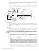
MULTI-POINT PROGRAMMABLE MIXER There are 2 Multi-Point Programmable Mixers in the ACRO system. They are Prog.Mix1 and Prog.Mix2. They differ from the standard mixers in that they allow a non-linear mix response from the Master to the Slave. This is possible because the mixer uses 7 points to define how the slave channel moves as the Master is moved. As the Master comes across each point, the Slave response can defined in terms of deflection and direction independent of other point settings.
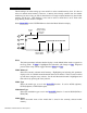
Master Channel [PROG.Mix1] THRO THRO LIST THRO AILE ELEV SW SELECT FLAP AUX3 THRO AUX2EXP #AIL #ELE #RUD CLR STK INH OFF RTRM RLVR SNPT IN 50 OUT 0 ENT Point-0 -100 Point-1 INH RUDD GEAR INH Point-2 AUX4 #THR 0 Point-3 LTRM LLVR INH Point-4 CANCELINH Point-5 Point-6 +100 0 1 2 3 4 5 6 Master Channel List. # Entries indicate bypassing D/R & Exp settings. Slave Channel – (Multi-Point Mixer) This is the Slave channel that will move according to the program mix in relation to the Master channel.
Point Names/Numbers – (Multi-Point Mixer) The points that can be adjusted are listed vertically by name and are also displayed by number along the bottom of the graph. Change the value of a point by highlighting and selecting the point name and dialing-in the desired percentage. Current Point Setting – (Multi-Point Mixer) This list shows the setting for each of the 7 adjustable points (Point-0, 1, 2, 3, 4, 5, 6).
Curve/Line – (Multi-Point Mixer) The Curve/Line is the line that results from connecting all of the points together based upon their point values. The default curve is a straight line that is on a 45-degree angle. This configuration is said to be Linear because there is an equal and constant relationship between the Master channel position and servo movement. When the master channel moves 10% of its travel, the slave channel moves 10% of its travel.
Throttle Used As Switch – (Multi-Point Mixer) The throttle stick may also be used as a switch to turn the mixer On and Off. It can be used by itself or in conjunction with one or more switches. To use the throttle as a switch, highlight and select THRO STK. Then use the rotary to dial-in a throttle stick percentage/position where 1 = lowest throttle position and 100 = full throttle position. The throttle trim does not affect the setting.
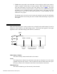
MULTI-POINT MIXER – Example: ELIMINATE PITCH-COUPLING (Rudd - Elev Mixing) The example below demonstrates a Multi-Point Program Mix for aircraft that pitch towards the landing gear when holding rudder for knife-edge flight – commonly known as Pitch-Coupling. If a mix is set up to provide an appropriate amount of up elevator for different amounts of rudder input, the aircraft will fly straight without pitching to the gear while holding rudder during knifeedge flight.
5. Set Points for Travel and Direction. There are 7 points along the travel of the rudder (the line that is intersected by the vertical line that moves right and left with the rudder stick). At each point an elevator deflection may be defined. A point that is set to 0% represents no elevator deflection at that point. A negative value at a point typically indicates Up elevator movement while a positive value results in Down elevator movement.
FAIL SAFE Fail Safe is available only when SPCM has been selected as the Modulation Type in the SYSTEM Menu. Obviously, the receiver must be of the PCM variety, as Fail Safe does not function in the PPM/FM mode. Fail Safe will appear in the FUNCTION List only if SPCM has been selected as the modulation type in the MODULAT function of SYSTEM Menu. When interference occurs on the frequency of operation, PCM receivers do not pass the interference on to the servos.
Channel Status – (Fail Safe) The status of each channel with regard to Fail Safe or HOLD is shown directly beneath each channel. When the indicator is in the upper position the channel is in F.S. and will return to a predetermined position if the receiver should go into Fail Safe. When the indicator is in the lower position, the channel will hold it's last good input.
TRAINER – TRAINER SYSTEM The XP9303 incorporates a Trainer System that allows the instructor to transfer some or all of the primary flight control functions (Throttle, Aileron, Elevator and Rudder) to the student. It also allows for indicating if the transmitter (TX) is to be the Master (controlled by the instructor) or Slave (controlled by the student). The Snap Roll button is used to transfer control to the student when the XP9303 is being used as the Master/Instructor transmitter.
CLR Button – (Trainer System) Pressing the CLR button will reset all channels to MAST. LIST Button – (Trainer System) Press the LIST button to return to the FUNCTION List, or rotate the rotary selector until LST appears next to LIST and select it to return to the SYSTEM Menu. ENT Button – (Trainer System) Pressing the ENT button returns to the Main Display. USING THE XP9303 FOR TRAINING – (Trainer System) 1. Connect the Trainer cord between the Master and Slave transmitters.
TIMER – TIMER SYSTEM The XP9303 contains a Timer System that includes three timers. One is an integrated timer that keeps track of total time that the TX has been on for the model and it is displayed on the Main display. The other timer can be configured as either a Countdown timer or as a Stopwatch. This timer also appears on the Main display when active and can be started, stopped and reset from the Main display.
Press the LIST button to return to the FUNCTION List, or rotate the rotary selector until LST appears next to LIST and select it to return to the SYSTEM Menu. ENT Button– (Timer) Pressing the ENT button returns to the Main Display. MONITOR The Monitor function provides a real-time display of channel movement when sticks, levers and switches are moved. It renames channels according to dual channel and other special assignments to assist in identifying the channel that is moving.
Monitor Mode – (Monitor) The Monitor mode identifies the display. It defaults to TRIM where the current settings of the digital trims are displayed. Highlighting and selecting TRIM changes the Monitor mode to MONI where the channel positions and movements are displayed. This parameter toggles between TRIM and MONITOR when selected. Function Name ENT LIST Channels [MONITOR] MONI CLR THRO AILE ELEV RUDD Monitor Mode- TRIM or MONI GEAR FLAP AUX2 AUX3 AUX4 Current Position of each channel.