THE AIRCRAFT SYSTEM - AIRPLANE MODE ULTIMATE HELICOPTER SYSTEM - HELICOPTER MODE RADIO CONTROL AIRCRAFT SYSTEM - GLIDER MODE SYSTEM 10 MODEL MEMORY 3 MODEL TYPE S • Z PCM/PPM SELECTABLE USER MANUAL 8 CHANNELS
XP8103 2
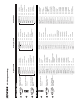
ENT UP – MODE – DN ON ENT 3 2 1 ENT UP – MODE – DN ENT UP – MODE – DN ON Function Mode 3 2 1 UP – MODE – DN Scroll through the functions using one of these buttons. Push these two buttons simultaneously. Turn the power switch ON (up). Scroll through options using one of these buttons. Turn the power switch ON (up). Push these two buttons simultaneously and hold. System Set-Up Mode [INFO-DISP] ↕ Data Transfer between traqnsmitters Pg.
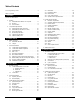
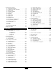
Table of Contents 1-2-3 Programming Charts . . . . . . . . . . . . . . . . . . . . . . . . . 3 3.8 3.9 3.10 3.11 3.12 Table of Contents . . . . . . . . . . . . . . . . . . . . . . . . . . . . . . . 4 I. I. Introduction Introduction How to Use This Manual . . . . . . . . . . . . . . . . . . . . . . . . . . . 8 4. Function Mode Functions 4.1 Dual Rate, Exponential. . . . . . . . . . . . . . . . . . . 36 4.2 Automatic Dual Rate, Exponential . . . . . . . . . . . 37 4.3 Reverse Switch . . . . . . . . . . . .
4. Function Mode Functions 4.1 Dual Rate, Exponential. . . . . . . . . . . . . . . . . . . 73 4.2 Automatic Dual Rate, Exponential . . . . . . . . . . . . 74 4.3 Reverse Switch . . . . . . . . . . . . . . . . . . . . . . . . 75 4.4 Sub-Trim Adjustment . . . . . . . . . . . . . . . . . . . . 75 4.5 Travel Adjust . . . . . . . . . . . . . . . . . . . . . . . . . 76 4.6 Stunt Trim. . . . . . . . . . . . . . . . . . . . . . . . . . . . 76 4.7 Throttle Hold . . . . . . . . . . . . . . . . . . . . . . . . . 77 4.
XP8103 6
I.
1. How To Use This Manual In the beginning of this manual you will find the specifications for the radio and its various accessories. In addition, guidelines for the initial installation of the accessories have been included. For your convenience, this manual is arranged with a separate sections for airplane, helicopter and glider software functions: Airplane Software: Page 21 Helicopter Software: Page 57 Glider Software: Page 99 A blank data sheet has been included at the end of each section.
2.2 Receiver NER-649S (PCM Systems) NER-549 (FM Systems) • This is a high performance PCM-FM single conversion receiver with 10 KHz super narrow band ABC&W circuitry. • The NER-549 is a high performance FM single conversion receiver with 10 KHz super-narrow band ABC&W circuitry. • The latest “S” type Central Processing Unit (CPU) is used in the PCM receiver. The new NER-649S offers the highest resolution available in any receiver.
3. Component Specifications 3.
3.3 Servo Specifications 507 517 531 Torque (oz./in.) 40.3 40.3 51.0 Speed (sec./60°) .25 .25 .23 Weight (oz.) 1.47 1.58 1.50 Size (in.) (W x L x H) 1.52 x 0.73 x 1.32 1.52 x 0.73 x 1.32 1.52 x 0.73 x 1.32 Single Single 3-Pole Ferrite 3-Pole Ferrite BB Motor N/A 3-Pole Ferrite 3.
XP8103 12
II.
4. Battery Charging 4.1 Transmitter/Receiver Note: It is imperative that you fully charge both the transmitter and the receiver battery packs prior to each flight. To do so, leave the charger and batteries hooked up overnight (16 hours). The first charge should be approximately 20–24 hours in order to fully charge both battery packs to peak capacity. Transmitter Back of Transmitter D.S.
5. General Information 5.1 Control Stick Length Adjustment The XP8103 allows you to adjust the control sticks’ length. Note: Turn the wrench counterclockwise to loosen the screw. Then, turn the stick clockwise to shorten or counterclockwise to lengthen. After the control stick length has been adjusted to suit your flying style, tighten the 2 mm set screw. Loosen Tighten To adjust the stick length, use the 2 mm Allen wrench (supplied with your XP8103 transmitter) to unlock the set screw.
5.3 Transmitter Rear Transmitter Module When the transmitter module is removed, you will find that the fuse is located at the bottom of the module cavity for easy replacement. DSC/Trainer Jack Charging Jack for Nicad Battery Only (8N600S) Battery Cover (Removed) Caution: The battery connector is keyed so that it can only be plugged in in one direction. Do not force.
5.4 DSC Cord For proper DSC hook up and operation: 1. Leave the transmitter power switch in the OFF position. The transmitter will not transmit any radio frequency (RF) in this position. 2. Plug the DSC cord (optional) into the DSC port in the rear of the transmitter. 3. The encoder section of the transmitter will now be operational and the LCD display will be lit. 4. Plug the other end of the DSC cord into the receiver charge receptacle. Turn the switch harness to the ON position.
5.7 Frequency Notes/Aircraft Only Frequencies The XP8103 employs a plug-in module system for transmitter frequency changes. If you want to change a frequency, you can simply change the radio frequency (RF) module, commonly referred to as either an RF module or transmitter module. The JR modules are universal for all modular frequency controlled systems. In other words, if you currently own a modular JR system, you can use the RF module from your current system with the XP8103.
5.9 Screen Contrast Adjustment The screen contrast adjustment feature of the XP8103 allows the user to select the proper tint of the screen for improved clarity and visibility in all weather conditions and temperatures. power switch ON and press the SEL and DATA + keys simultaneously. To decrease the contrast (lighten the screen), press the SEL and DATA - keys simultaneously. To increase the contrast (darken the screen), simply turn the 5.
XP8103 20
III.
1. Transmitter Controls 1.1 Control Identification and Location Antenna LCD Display (Do Not Press) Carrying Handle Aux 2 Knob Aux 3 Knob Snap Roll/ Timer/Trainer Switch P.
Airplane Version Transmitter – Heli Mode Antenna Carrying Handle LCD Display – DO NOT PRESS Pitch Trim Knob Hovering Pitch Knob Trainer/Timer Switch Throttle Hold Switch Invert Switch Rudder Dual Rate Switch Elevator Dual Rate Switch Aileron Dual Rate Switch Flight Mode Switch N-Normal Position 1-Flight Mode 1 2-Flight Mode 2 Hovering Throttle Knob Throttle Trim Elevator Trim Aileron/Elevator Stick Throttle/Rudder Stick Neck Strap Eyelet Aileron Trim Rudder Trim Channel Assignment 1. 2. 3. 4.
1.2 Connections ® 4N600 Aux Channel 4.8V 600mAh JAPAN REMOTE CONTROL CO., LTD.
2. General Information 2.1 Input Key Functions • You will hear a clicking (beeping) sound to confirm input has been achieved. • The SEL keys or CH keys are used to scroll through, or manipulate functions within a specific program or display. • Except for the CLEAR key, the AUTO advance system (two speed scrolling) is active when you continue pressing down on a key.
2.2 Normal Display, cont. From the Normal Display, the following inputs can be made: When setting various functions with the buttons shown below, start either in the Function Mode or the System Set-Up Mode.
3.2 Function Mode From Normal Display, press the UP and DN keys simultaneously to enter the Function Mode. In this mode, by using the UP or DN keys, the desired functions can be selected. When channel selection or an additional function change is desired, use the CH keys or SEL key. For example, Dual Rate Function is selected and the elevator channel is displayed by pressing the UP key once; the function is changed to the next mode, Reverse Switch, but the channel is still displayed as elevator.
3.3 List Mode (Function Mode) To enter the List Mode, press the DN and SEL keys simultaneously. From this display, pressing the UP and DN keys simultaneously will move the system from the list mode to the Press simultaneously to access function at cursor UP DN function shown at the cursor. Note that the cursor is moved by the UP and DN keys. Press to select either of two Function List screens SELECT CH CH CLEAR Inactive while in List Mode screen 3.
3.5 Copy Select Function (System Set-Up Mode) The Copy Select Function enables you to copy all of the settings of your current model to another memory (model number) within the same transmitter. This is very useful when setting up one aircraft several different ways. existing model number model names (if dot is shown, model name is blank) model number to be transferred to.
3.7 Model Type Selection (System Set-Up Mode) The XP8103 is capable of performing as a helicopter, airplane or glider radio with full functions for each. It can also memorize data for 10 models individually. Note: If the power switch is turned OFF immediately after selecting the new model type, the change will not be saved. To change and save the model type press the UP or DN keys, or press UP and DN keys or DN and SEL keys simultaneously.
3.9 Modulation Select (System Set-Up Mode) The Modulation Selection Function enables your XP8103 to transmit to a variety of JR receivers that are already, or may soon be, in existence. You can select from either S-PCM or Z-PCM mode, depending on the Central Processing Unit within your receiver, or from PPM (Pulse Position Modulation—FM). Refer to the receiver compatibility chart for the correct modulation.
3.10 Data Transfer (System Set-Up Mode) This function is used to transfer all existing memorized data for a model from one XP8103 transmitter to another XP8103 transmitter. Caution: Please use special caution when copy function is activated as existing data is replaced with new data. Use the + and - keys to select models to be transferred and activate by pressing the CLR key. Caution: When the battery alarm is activated (battery low), the copy function is not operational.
3.10 Data Transfer, cont. When there is a data receiving failure during transmitting, the counter will stop. At this time, press the CLR key to stop the receiving condition. Check to be sure the receiving counter is operating normally and ended with 100%.
3.11 Wing Type Selection (System Set-Up Mode) The purpose of Wing Mixing or Wing Type Function is to eliminate mechanical or programmable mixes that would otherwise be necessary for the proper flight of certain styles of aircraft. There are three wing types from which to choose; select the one that best suits your R/C aircraft. They are as follows: Normal, flaperon, and elevon (delta). Each of the wing type selections will be covered in a separate section.
3.11 Wing Type Selection (System Set-Up Mode), cont. Flaperon Wing Type Connections Elevon Wing Type Connections ELEV servo port (right aileron) AILE servo port (left aileron) AILE servo port (right aileron) AUX 1 servo port (left aileron) 3.12 Spoiler Channel Input Selection (System Set-Up Mode) The purpose of the Spoiler Channel Input Selection Function is to assign the activation device for the AUX2 channel.
4. Function Mode Functions 4.1 Dual Rate, Exponential (Function Mode) Dual rates are available for the aileron, elevator and rudder channels of your R/C airplane. The amount of travel is adjustable from 0-125%; exponential is adjustable from 0% (LIN) to 100% in 1% increments. The factory setting, or default value, for both the 0 and 1 switch positions is 100%. Either switch position may be selected as the low or high rate by placing the switch in the desired position and adjusting the value accordingly.
4.2 Automatic Dual Rate, Exponential (Function Mode) When the Automatic Rudder Dual Rate Function is active, the throttle stick position automatically switches among the rudder dual rates that you have selected in the Dual Rate Function. This means that, as you advance or pull back the throttle stick, the rudder travel rates automatically change.
4.3 Reverse Switch (Function Mode) The Reverse Switch is an electronic means of reversing the throw (direction) of a given channel (servo). All eight channels of the XP8103 offer reversible servo direction. This will ease set-up during servo installation in your aircraft. In Function Mode, use the UP or DN key to select the Reverse Switch function and access by pressing the UP and DN keys simultaneously.
4.5 Travel Adjust (Function Mode) The purpose of Travel Adjust, also known as endpoint adjustment or adjustable travel volume, is to offer you precise servo control deflection in either direction of servo operation. The travel adjust range is from 0-150% (0 degrees to 60 degrees) from neutral and it can be adjusted for each direction individually. The factory default (data reset) value is 100% for each direction of servo travel.
4.7 Aileron to Rudder Mixing (Function Mode) This form of mixing is designed so that when input to the aileron stick is given, the rudder servo will also move, eliminating the need to coordinate these controls manually. When adjusting, if an opposite mixing direction of the rudder servo is required, simply press the + or - key and change the mixing value from + to - or - to +. This will reverse the mixing direction of the rudder from its original direction.
4.8 Landing System (Function Mode) The purpose of the landing system is to set the aircraft in a landing attitude for more consistent landings. This is accomplished by selecting values for the elevator, flap and spoiler — AUX 2 (if active) — to be activated when the land switch is engaged. Note that the spoiler (AUX 2) can be mixed in with the elevator and flap landing attitudes, but only in the deployed or retracted positions.
4.8 Landing System (Function Mode), cont. To activate the Automatic Landing feature (refer to Figure B): either the + or - key to activate the Automatic Landing System. To change this value, move the stick to a new position and press the + or - key. To clear the auto land point, press CLR and the display will return to INH. 1. From the Spoiler value setting, press either the left or right CH key, moving the cursor to AUTO. 2.
4.9 Snap Roll (Function Mode), cont. Snap Roll Direction Change Once the snap rolls are established in the Function Mode, they can be selected using the UP/DN and +/- keys located on the front of the transmitter while in the normal display. Refer to Figure 4.9C. The adjustable range for each function is 0-125%; the factory default is 100%. When the Snap Roll Function is active, the direction will be indicated in the normal display (figure C). (4.9A) (4.
4.9 Snap Roll (Function Mode), cont. (4.9C) Note: Display will change when Snap Roll direction changes are made.
4.11 Trim Offset Memory (Function Mode) The Trim Offset Memory Function allows you to test fly your aircraft and correct for any built-in trim requirements. After you adjust the aileron, elevator and/or rudder trim levers during test flights, the trim levers are no longer in their center, or neutral, positions. The use of trim offset allows you to return them to their central or neutral positions without readjusting the linkages.
4.11 Trim Offset Memory (Function Mode), cont. 4 1 5 2 3 4.12 Flap Knob Adjustment (Function Mode) Flap Knob Operating Adjustment The Flap Knob Operating Value Adjustment Function allows adjustment of the operational value of the flap channel (AUX 1) using the flap adjustment knob. The factory preset values are as follows: Trim 30%; INH 0%; and Full 100%. These are merely starting points. They can be changed to any value using the + or - keys. This function makes fine tuning of the flaps very easy.
4.13 Programmable Mixing (1-6) (Function Mode) Accessing the Programable Mixing Functions Place the transmitter power switch in the ON position. Press the Mode UP and DN keys simultaneously to enter the Function Press the UP and DN keys simultaneously to enter/exit the Function Mode UP To Programmable Mixing 2 To Flap POT Adjustment function DN Mode. Press either the UP or DN keys until PROG. Mix 1 appears in the upper left portion of the LCD (refer to figure below).
4.13 Programmable Mixing (1-6) (Function Mode), cont. Assigning Channels Assigning Mixing Values Using the SEL key, move the cursor to the left of the master channel. Press the left or right CH keys to position the cursor below the master or slave channel. Press the + or - keys to select the desired channels. Position the cursor to the left of “Point” and press the left or right CH keys to reverse the position point. Increase or decrease the mixing value using the + or - keys or the CLR key.
4.13 Programmable Mixing (1-6) (Function Mode), cont. Exponential Function Mixing with Trim An exponential function allows you to "smooth" the selected curve. With the cursor at the “point” position, press the left or right CH key until EXP is indicated. Exponential is activated by pressing either the + or - key (Refer to figure 4.13C). Whenever the master channel is aileron, elevator, rudder, or throttle, you have the option of allowing the master channel’s trim lever to mix into the slave channel.
4.14 Fail-Safe/Hold (Function Mode) The Fail-Safe/Hold Function is available only when you use the XP8103 transmitter in either of the PCM modulations — S-PCM or Z-PCM. This function is designed to help minimize damage to your airplane during a loss of signal to the receiver. The servos either assume the fail-safe presets or hold the last good signal position.
4.14 Fail-Safe/Hold (Function Mode), cont. 3. Hold the transmitter sticks in the position that you want the servos to assume during signal loss conditions. You can determine fail-safe preset positions for the other channels by placing the potentiometers and switches in the positions that you want them to assume during interference. 4. With the sticks, switches and potentiometers in the fail-safe positions, touch the CLR key. This will enter these locations as the fail-safe memory settings.
4.14 Fail-Safe/Hold (Function Mode), cont. “hold” or “preset” fail-safe condition which is determined by positioning the particular control and pressing the CLR key. The transmitter will memorize the switch fail-safe position and automatically transfer the setting to the receiver. Setting the Fail-Safe/Hold Memory in S-PCM Modulation 1. After accessing the Fail-Safe Function, it is time to adjust the fail-safe presets. 2. Select all of the channels for which you want to enter a failsafe preset.
4.15 Trainer (Function Mode), cont.
4.16 Timer (Function Mode) The XP8103 offers two separate types of timer functions — countdown and stopwatch. In the countdown mode, the transmitter will beep at 30 seconds. At zero, the time will begin counting up with a + indication. Up count will count up to 59:59 (59 minutes 59 seconds). Count start and stop operations are activated by the snap roll/trainer switch. But when using it as the trainer’s master transmitter, start/stop by this switch is inhibited.
4.17 Servo Output Indicator (Function Mode) This function displays each servo’s operating value. Each bar center indicates neutral position. Left or right dots indicate 50%, 100% and 150%. Note: All indications are actual positions including adjustments and mixing. It is also possible to view servo travel/servo directions when mixing functions are activated.
XP8103 DATA SHEET ACRO SPCM • ZPCM • PPM FAIL-SAFE (SPCM • ZPCM) DIFFERENTIAL ACRO 56
IV.
1. Transmitter Controls 1.
Helicopter Version Transmitter–Airplane Mode Antenna Carrying Handle LCD Display – DO NOT PRESS Aux 3 Flap Trim Knob Timer/Snap Roll/Trainer Switch Mixing Switch Landing Mode Switch Rudder Dual Rate/AUX 2 Switch Elevator Dual Rate Switch Aileron Dual Rate Switch AUX 2 Knob Gear/Mixing Switch Throttle Trim Elevator Trim Elevator/Aileron Stick Throttle/Rudder Stick Neck Strap Eyelet Aileron Trim Rudder Trim Power Switch Channel Assignment 1. 2. 3. 4. 5. 6. 7. 8.
1.2 Switch Warning Safety Feature (Helicopter Mode) When the XP8103 transmitter is operated in the helicopter mode, there is a warning system that is employed to avoid accidental operation when the power switch is initially turned ON. will return to normal. Note: If the inverted and throttle hold switch functions are not activated prior the power switch being turned ON, no alarm will sound.
1.4 Gyro Connections Connect the gyro to the axis to be controlled (commonly rudder channel) per the illustration below. The gyro unit should be mounted as close as possible to the center of gravity of the helicopter (near the main shaft) at a position where vibration is minimal. Please refer to the specific gyro/helicopter instructions for proper gyro placement and installation.
2. General Information 2.1 Input Key Function • You will hear a clicking (beeping) sound to confirm input has been achieved. • The SEL keys or CH keys are used to scroll through, or manipulate functions within a specific program or display. • Except for the CLEAR key, the AUTO advance system, (two speed scrolling) is active when you continue pressing down on a key.
2.2 Normal Display, cont. From the Normal Display, the following inputs can be made: When setting various functions with the buttons shown below, start either in the Function Mode or the System Set-Up Mode.
3. System Set-Up Mode Functions 3.1 System Set-Up Mode To set the System Set-Up Mode, press the UP and DN keys simultaneously and turn the power switch from OFF to ON. Functions are selectable by pressing either the DN or UP keys. Individual settings are explained later at each function. In this mode, servos are not activated, but operating signals are transmitting (only when the Tx module is in place). However, use extra caution not to interfere with other frequencies.
3.2 Function Mode From Normal Display, press the UP and DN keys simultaneously to enter the Function Mode. In this mode, by using the UP or DN keys, the desired functions can be selected. When channel selection or an additional function change is desired, use the CH keys or Select key. For example, Dual Rate Function is selected and the elevator channel is displayed by pressing the UP key once; the function is changed to the next mode, Reverse Switch, but the channel is still displayed as elevator.
3.3 List Mode To enter the List Mode, press the DN and SEL keys simultaneously. From this display, pressing the UP and DN keys simultaneously will move the system from the list mode to the Press simultaneously to access function at cursor UP function shown at the cursor. Note that the cursor is moved by the UP and DN keys. Press to select either of two Function List screens SELECT DN CH CH CLEAR Inactive while in List Mode screen 3.
3.5 Copy Select Function (System Set-Up Mode) The Copy Select Function enables you to copy all of the settings of your current model to another memory (model number) within the same transmitter. This is very useful when setting up one aircraft several different ways. existing model number model names (if dot is shown, model name is blank) model number to be transferred to.
3.7 Model Type Selection (System Set-Up Mode) The XP8103 is capable of performing as a helicopter, airplane or glider radio with full functions for each. It can also memorize data for 10 models individually. Note: If the power switch is turned OFF immediately after selecting the new model type, the change will not be saved. To change and save the model type press the UP or DN keys, or press UP and DN keys or DN and SEL keys simultaneously.
3.9 Modulation Select (System Set-Up Mode) TThe Modulation Selection Function enables your XP8103 to transmit to a variety of JR receivers that are already, or may soon be, in existence. You can select from either S-PCM or Z-PCM mode, depending on the Central Processing Unit within your receiver, or from PPM (Pulse Position Modulation—FM). Refer to the receiver compatibility chart for the correct modulation.
3.10 Data Transfer This function is used to transfer all existing memorized data for a model from one XP8103 transmitter to another XP8103 transmitter. Caution: Please use special caution when copy function is activated as existing data is replaced with new data. Use the + and - keys to select models to be transferred and activate by pressing the CLR key. Caution: When the battery alarm is activated (battery low), the copy function is not operational.
3.10 Data Transfer, cont. When there is a data receiving failure during transmitting, the counter will stop. At this time, press the CLR key to stop the receiving condition. Check to be sure the receiving counter is operating normally and ended with 100%.
3.11 Input Selection Function (System Set-Up Mode) Aux 2 (Channel #7) Input Selection The Aux 2 Channel Input Selection Function allows you to select which switch, pitch trim knob, or throttle hold switch will activate the Aux 2 Function. If you are using the Aux 2 Function (channel #7) for remote gyro sensitivity, JR TEC-1000 carburetor operation, etc., this function should remain in the factory INH position. change the rudder dual rate and the gyro sensitivity at the same time.
4. Function Mode Functions 4.1 Dual Rate, Exponential (Function Mode) Dual rates are available for the aileron, elevator and rudder channels of your R/C helicopter. The amount of travel is adjustable from 0-125%; exponential is adjustable from 0% (LIN) to 100% in 1% increments. The factory setting, or default value, for both the 0 and 1 switch positions is 100%. Either switch position may be selected as the low or high rate by placing the switch in the desired position and adjusting the value accordingly.
4.2 Automatic Dual Rate, Exponential (Function Mode) When the Automatic Dual Rate function is activated (ACT), when switching the Flight Mode switch to Stunt 1 or Stunt 2, or when switching the throttle hold switch ON, the Aileron, Elevator, and Rudder channel dual rate values can be switched to the values set for dual rate position #1.
4.3 Reverse Switch (Function Mode) The Reverse switch is an electronic means of reversing the throw (direction) of a given channel (servo). All eight channels of the XP8103 offer reversible servo direction. This will ease set-up during servo installation in your aircraft. In Function Mode, use the UP or DN key to select the Reverse Switch function and access by pressing the UP and DN keys simultaneously.
4.5 Travel Adjust (Function Mode) The purpose of Travel Adjust, also known as endpoint adjustment or adjustable travel volume, is to offer you precise servo control deflection in either direction of servo operation. The travel adjust range is from 0-150% (0 degrees to 60 degrees) from neutral and it can be adjusted for each direction individually. The factory default (data reset) value is 100% for each direction of servo travel.
4.6 Stunt Trim (Function Mode), cont. Press the UP and DN keys simultaneously to enter/exit the Function Mode UP DN Press the DN and Select keys simultaneously to access the Function Mode List Display SELECT CH To Throttle Hold function CH Press to move the arrow to the channel to be adjusted To Travel Adjust function CLEAR Press to increase or decrease the mixing value ( ±125%) Press to reset the mixing value at the arrow to the factory pre-set (0) or to inhibit the Stunt Trim function 4.
4.8 Throttle Curve (Function Mode) The XP8103 offers three (3) separate throttle curves with five (5) adjustable points per curve. This function allows you to customize the throttle curve and pitch curve together to maximize engine performance at a particular pitch setting. Once the throttle curves are established, each can be activated in flight using the three (3) position flight mode switch. The flight switch offers three (3) selectable curves.
4.8 Throttle Curve (Function Mode), cont.
4.8 Throttle Curve (Function Mode), cont. Exponential Throttle Curve Function With the XP8103 system, individual throttle curves are selectable to be either straight (linear) or curved (exponential). To select an exponential curve, press either of the CH keys until EXP OFF appears on the throttle curve screen. Next press either the + or - UP DN SELECT CH key to activate the exponential feature (an “on” will replace the “off” on the screen).
4.9 Pitch Curve (Function Mode) Adjustment of the pitch curve is very similar to the throttle curve adjustment described in the preceding section. A thorough understanding of the throttle curve section will make pitch curve adjustment easier to understand. The XP8103 offers four (4) independent types of pitch curves: Normal, Stunt 1, Stunt 2 and Hold. Each pitch curve contains five (5) adjustable points — L, 1, 2, 3, and H.
4.9 Pitch Curve (Function Mode), cont. Example of Throttle Curve and Pitch Curve Settings An example of throttle curve and pitch curve settings for aerobatic specifications are shown below in the form of graphs. Details of the curves will differ, depending on the helicopter specifications. In these examples, the throttle open-close stroke and autorotation pitch stroke are set from 0 to 100.
4.10 Inverted Switch (Function Mode) The purpose of the Inverted Switch Function is to electronically reverse several control directions to enable you to fly a helicopter much more easily inverted. When the inverted switch is pulled down, the inverted flight function is switched ON. When this function is not in use, the display shows INH as below. If you do not intend to use the inverted function, leave this operation inhibited.
4.10 Inverted Switch, (Function Mode) cont. Press the UP and DN keys simultaneously to enter/exit the Function Mode UP DN Press the DN and Select keys simultaneously to access the Function Mode List Display SELECT CH CH To Revolution/Acceleration Mixing Function CLEAR Press the + or - keys to increase/decrease the offset value To Pitch Curve function Press to inhibit the Inverted Switch Function 4.
4.11 Revolution/Acceleration Mixing, (Function Mode) cont. Acceleration Mixing Rudder Offset Setting During Throttle Hold The Acceleration Mixing function is provided to compensate for the main rotor accelaration (and deceleration) torque. The magnitude and duration of the signal to the tail rotor depends upon rate of the throttle changes. Thus, quick, jerky throttle inputs will yield more noticeable tail compensation.
4.12 Gyro Sensitivity Adjustment (Function Mode) cont. two pre-determined settings through the use of the flight mode switch. As different flight modes are selected (Normal, 1, 2, Hold), the Gyro’s sensitivity rate will switch to the pre-determined compensation rate for each particular flight mode in use. 5.
4.12 Gyro Sensitivity Adjustment, (Function Mode) cont. JR NEJ-1000 Piezo Gyro Automatic Gyro Sensitivity Adjustment Manual Gyro Sensitivity Adjustment 1. Connect the white connector from the NEJ-1000 remote gain controller to the AUX 2 channel of the receiver. 1. Connect the white connector from the NEJ-1000 remote gain controller to the AUX 2 channel of the receiver. 2. Select the Manual Gyro Sensitivity Feature (“RUDD D/R” will appear on the screen). 3.
4.13 Programmable Mixing 1-3 (Function Mode), cont.
4.13 Programmable Mixing 1-3 (Function Mode), cont.
4.13 Programmable Mixing 1-3, (Function Mode) cont.
4.13 Programmable Mixing 1-3 (Function Mode), cont. Rate Adjustment Programmable Mixing Offset The Rate Adjustment Function found in the Programmable Mix #3 Function allows you to increase or decrease the amount of mixing (servo travel) given to the slave channel in either the high/low, or left/right positions. Adjustment of this value will only affect the mixing value (output) of the slave channel, and it has no effect on the servo output value of the master channel.
4.14 Fail-Safe/Hold, cont. When the Fail-Safe Function is activated (i.e., when the signal is interrupted), the transmitter automatically moves each servo to a preset position. The position that each servo assumes is determined by you, as is the time length of interference that must occur before servo movement. After the interference has ceased, control of the airplane returns immediately to you. There are three time delays to choose from: 1/4 (0.25) second, 1/2 (0.50) second and 1.0 second.
4.14 Fail-Safe/Hold, cont. Note: If Fail-Safe does not appear on your LCD, it is because you are transmitting in PPM. Fail-Safe is not applicable in the PPM mode. Refer to the Modulation Mode Selection Section for more information. Setting the Fail-Safe/Hold Memory in S-PCM Modulation Fail Safe/Hold Combination in S-PCM Modulation 2. Select all of the channels for which you want to enter a failsafe preset.
4.15 Trainer (Function Mode) The XP8103 transmitter employs two separate types of trainer systems: 3. Switch the master transmitter ON. Do not switch on the slave transmitter; you must only have the master transmitter ON. A. Normal trainer system — all functions are controlled by either the master transmitter or the slave transmitter. B. Programmable function trainer — stick functions may be assigned to the slave one at a time.
4.15 Trainer (Function Mode), cont. The normal display screen will show the type of trainer function selected once the trainer function is activated B. Use of Programmable Trainer Function In this mode, the master may assign functions to the student one at a time to make learning to fly easier. For example, the master may assign the slave rudder and elevator.
4.16 Timer (Function Mode), cont. Inhibit Accumulated time minutes hours Countdown Timer Stopwatch Countdown timer setting time (0.00 to 59.
4.17 Servo Output Indicator (Function Mode) This function displays each servo’s operating value. Each bar center indicates neutral position. Left or right dots indicate 50%, 100% and 150%. Note: All indications are actual positions including adjustments and mixing. It is also possible to view servo travel/servo directions when mixing functions are activated.
XP8103 DATA SHEET HELI MODEL NO. ____________________________________ MODEL NAME __________________________________ MODULATION SPCM - ZPCM - PPM ________________ AILE ELEV RUDD D/R % % % EXP % % % D/R % % % EXP % % % AUTO D/R (POS. 1) 0 DUAL-RATE • EXP 1 STUNT TRIM INPUT SEL INH • ACT THRO NORM • REV REVERSE SW ST1 INH • ACT ST2 INH • ACT ST2 INH • ACT AUX2 HOLD SW• PIT.
V. Glider Section Important: Before installing your servos in your glider's wing, see page 134, Servo Installation Section. Note: The Practical Application Section on page 134 provides a step-by-step procedure on programming a 5 or 6 servo equipped glider. Reference to this section is highly recommended prior to setting up your glider.
1. Transmitter Controls 1.
Airplane Version Transmitter – Airplane Mode Antenna Carrying Handle LCD Display – DO NOT PRESS Aux 2 Knob Snap Roll/ Timer/Trainer Switch Aux 3 Knob P. Mix Switch/Aux 2 Gear Switch Rudder Dual Rate Switch Elevator Dual Rate Switch Aileron Dual Rate Switch Flap/Mixing Switch Flap Knob Throttle Trim Elevator Trim Aileron/Elevator Stick Throttle/Rudder Stick Neck Strap Eyelet Aileron Trim Rudder Trim Power Switch Input Keys Channel Assignment 1. 2. 3. 4. 5. 6. 7. 8.
1.2 Connections ® 4N600 Aux Channel not used Aux Channel AUX3 4.8V 600mAh JAPAN REMOTE CONTROL CO., LTD.
2. General Information 2.1 Input Key Functions • You will hear a clicking (beeping) sound to confirm input has been achieved. • The SEL keys or CH keys are used to scroll through, or manipulate functions within a specific program or display. • Except for the CLEAR key, the AUTO advance system (two speed scrolling) is active when you continue pressing down on a key.
2.2 Normal Display, cont. From the Normal Display, the following inputs can be made: When setting various functions with the buttons shown below, start either in the Function Mode or the System Set-Up Mode.
3.2 Function Mode From Normal Display, press the UP and DN keys simultaneously to enter the Function Mode. In this mode, by using the UP or DN keys, the desired functions can be selected. When channel selection or an additional function change is desired, use the CH keys or SEL key. For example, Dual Rate Function is selected and the elevator channel is displayed by pressing the UP key once; the function is changed to the next mode, Reverse Switch, but the channel is still displayed as elevator.
3.3 List Mode (Function Mode) To enter the List Mode, press the DN and SEL keys simultaneously. From this display, pressing the UP and DN keys simultaneously will move the system from the list mode to the Press simultaneously to access function at cursor UP function shown at the cursor. Note that the cursor is moved by the UP and DN keys. Press to select either of two Function List screens SELECT DN CH CH CLEAR Inactive while in List Mode screen 3.
3.5 Copy Select Function (System Set-Up Mode) The Copy Select Function enables you to copy all of the settings of your current model to another memory (model number) within the same transmitter. This is very useful when setting up one aircraft several different ways.
3.7 Model Type Selection (System Set-Up Mode) The XP8103 is capable of performing as a helicopter, airplane or glider radio with full functions for each. It can also memorize data for 10 models individually. Note: If the power switch is turned OFF immediately after selecting the new model type, the change will not be saved. To change and save the model type press the UP or DN keys, or press UP and DN keys or DN and SEL keys simultaneously.
3.9 Modulation Select (System Set-Up Mode) The Modulation Selection Function enables your XP8103 to transmit to a variety of JR receivers that are already, or may soon be, in existence. You can select from either S-PCM or Z-PCM mode, depending on the Central Processing Unit within your receiver, or from PPM (Pulse Position Modulation—FM). Refer to the receiver compatibility chart for the correct modulation.
3.10 Data Transfer (System Set-Up Mode) This function is used to transfer all existing memorized data for a model from one XP8103 transmitter to another XP8103 transmitter. Caution: Please use special caution when copy function is activated as existing data is replaced with new data. Use the + and - keys to select models to be transferred and activate by pressing the CLR key. Caution: When the battery alarm is activated (battery low), the copy function is not operational.
3.10 Data Transfer, cont. When there is a data receiving failure during transmitting, the counter will stop. At this time, press the CLR key to stop the receiving condition. Check to be sure the receiving counter is operating normally and ended with 100%.
3.11 Wing Type Selection (System Set-Up Mode) Use of V-Tail Connect the left moveable tail surfaces to the servo connected to ELEV and the right moveable tail surfaces to the servo connected to RUDD. At this time, the servo’s operational value is automatically set for 75%. An applicable channel’s servo travel is individually adjusted by each servo’s dual rate settings. Servo reversing is also set individually. Neutral adjustment should be made individually using the Sub-Trim Adjustment Function.
3.12 Input Selection, cont. Current Flap Channel Input Pot 6: Flap Knob FLP.SW+PG: Flap Switch and Pot 6 Press the UP and DN keys simultaneously to enter/exit the System Set-Up Mode UP DN Press the DN and Select keys simultaneously to access the System Mode info display SELECT CH CH To Model Select function CLEAR Press either the + or - key to select Pot 6 or FLP.SW +P6 To Wing Type function Press to reset Flap input to Pot 6 4. Function Mode Functions 4.
4.2 Reverse Switch (Function Mode) The Reverse Switch is an electronic means of reversing the throw (direction) of a given channel (servo). All eight channels of the XP8103 offer reversible servo direction. This will ease set-up during servo installation in your aircraft. In Function Mode, use the UP or DN key to select the Reverse Switch function and access by pressing the UP and DN keys simultaneously.
4.4 Travel Adjust (Function Mode) The purpose of Travel Adjust, also known as endpoint adjustment or adjustable travel volume, is to offer you precise servo control deflection in either direction of servo operation. The travel adjust range is from 0-150% (0 degrees to 60 degrees) from neutral and it can be adjusted for each direction individually. The factory default (data reset) value is 100% for each direction of servo travel.
4.5 Elevator To Flap Mixing (Function Mode), cont.
4.6 Aileron to Flap Mixing (Function Mode), cont.
4.7 Differential Aileron Mixing (Function Mode), cont.
4.8 Flap to Elevator Mixing (Function Mode), cont.
4.
4.10 Aileron to Rudder Mixing (Function Mode), cont.
4.11 Butterfly Mixing (Crow) (Function Mode), cont.
4.12 Dual Flap Trim (Function Mode), cont. Press the UP and DN keys simultaneously to enter/exit the Function Mode UP DN Press the DN and Select keys simultaneously to access the Function Mode List Display SELECT To Trim Offset Memory function CH CH Press either CH key to select the desired trim POT To Butterfly Mixing function →POT 5 ↓ POT 6 ↓ POT 7 Note: Only POT 5 will appear on the LCD unless the Dual Flap Mixing Function is activated in the Wing Mixing Function.
4.13 Trim Offset Memory (Function Mode), cont. Setting Trim Offset Example: aileron trim. Trim is offset to left. Access the Trim Offset Function and see Figure 1 below. At this time, press the + or - keys and the display shows (2) and memorizes the existing position. Next, return trim to center and press the CLR key. Display shows (3) and memorizes the trim offset value and the servo is returned to its first trim position.
4.14 Programmable Mixing (1-6) (Function Mode) Accessing the Programable Mixing Functions Place the transmitter power switch in the ON position. Press the Mode UP and DN keys simultaneously to enter the Function Press the UP and DN keys simultaneously to enter/exit the Function Mode UP To Programmable Mixing #2 To Flap POT Adjustment function DN Mode. Press either the UP or DN keys until PROG. Mix 1 appears in the upper left portion of the LCD (refer to figure below).
4.14 Programmable Mixing (1-6), cont. Assigning Channels Assigning Mixing Values Using the SEL key, move the cursor to the left of the master channel. Press the left or right CH keys to position the cursor below the master or slave channel. Press the + or - keys to select the desired channels. Position the cursor to the left of “Point” and press the left or right CH keys to reverse the position point. Increase or decrease the mixing value using the + or - keys or the CLR key.
4.15 Fail-Safe/Hold (Function Mode) The Fail-Safe/Hold Function is available only when you use the XP8103 transmitter in either of the PCM modulations — S-PCM or Z-PCM. This function is designed to help minimize damage to your airplane during a loss of signal to the receiver. The servos either assume the fail-safe presets or hold the last good signal position. This function stops (or holds) the servos in the positions they were in just prior to the interference.
4.15 Fail-Safe/Hold (Function Mode), cont. Setting Fail-Safe/Hold Memory in Z-PCM Modulation 1. After accessing the Fail-Safe Function, it is time to adjust the Fail-Safe presets. 2. Select among the three time delays (1/4, 1/2 or 1.0 seconds). To do so, simply press the + or - key until the appropriate delay appears on the screen. 1. Place the transmitter power switch in the ON (upper) position. 2.
4.15 Fail-Safe/Hold (Function Mode), cont.
4.16 Trainer (Function Mode) The XP8103 transmitter employs two separate types of trainer systems: 3. Switch the master transmitter ON. Do not switch on the slave transmitter; you must only have the master transmitter ON. A. Normal trainer system — all functions are controlled by either the master transmitter or the slave transmitter. B. Programmable function trainer — stick functions may be assigned to the slave one at a time.
4.16 Trainer (Function Mode), cont. The normal display screen will show the type of trainer function selected once the trainer function is activated B. Use of Programmable Trainer Function In this mode, the master may assign functions to the student one at a time to make learning to fly easier. For example, the master may assign the slave rudder and elevator.
4.17 Timer (Function Mode), cont. Inhibit Accumulated time minutes hours Countdown Timer Stopwatch Countdown timer setting time (0.00 to 59.
4.18 Servo Output Indicator (Function Mode) This function displays each servo’s operating value. Each bar center indicates neutral position. Left or right dots indicate 50%, 100% and 150%. Note: All indications are actual positions including adjustments and mixing. It is also possible to view servo travel/servo directions when mixing functions are activated.
5. Practical Applications 5.1 Setting Up Your Sailplane XP8103 Program and Mix Applications C. Landing Model Programming This section outlines the procedures and suggested basic mechanical set-up for gliders using a six servo flight system with each flap and aileron driven by a dedicated servo. The following will be outlined: D. Full Span Variable Camber Mixing A. Basic Mechanical Set-Up and Mixing (Aileron Differential and Coupled Aileron-Rudder) E.
5.3 Launch and Reflex Presets In the initial set-up of your XP8103 transmitter, if you set the flap control preference to SW+P6, the set-up of your Launch (and Reflex) presets is partially done for you. 1. Position the flap switch in the reflex (UP) position. This will make the flaps raise. Move to the TRVL ADJ. (Endpoint adjustment) portion of the Function Mode and adjust the flap up travel to the desired amount of reflex. Launch Preset 2.
5.4 Landing Mode Program, cont. arrow to SPOI OFFSET. With the trim tab centered and the left stick in position for neutral flap (low stick), press the CLR key to the right of the data keys. This stores your offset or neutral point. stabilizer with elevator will generally use a smaller percentage. 2. Use the CH key and go to SPOI-FLAP. Using the + or - keys, program the mix value to give 90 degrees of flap throw. It may be necessary to return to TRVL ADJ.
5.6 Special Mixing The open programmable mixes available in the XP8103 allow you to enhance your presets with a variety of mix applications. Another programming feature included in the XP8103 is the ability to assign a switch to use for the following mixes: All programmable mixes, Elevator-Flaperons, Aileron-Flaperons, Flaperons-Elevator, and Flaperons-Aileron. In addition, the latter two mixes also include a trim offset for the flap.
XP8103 DATA SHEET GLID SPCM • ZPCM • PPM FAIL-SAFE (SPCM • ZPCM) DIFFERENTIAL GLID 138
EXCLUSIVELY DISTRIBUTED BY HORIZON HOBBY DISTRIBUTORS, INC.
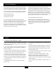
XP8103 Manual Addendum Please refer to the info below for clarification before using these functions. This information is applicable in all model types (Airplane, Helicopter, Glider). Manual Page Airplane 54 Helicopter 95 Glider 131 Timer (Function Mode) The XP8103 offers two separate types of timer functions — countdown and stopwatch. In the countdown mode, the transmitter will beep at 30 seconds. At zero, the time will begin counting up with a + indication.
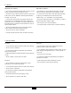
XP8103 Manual Addendum Please refer to the info below for clarification before using these functions. This information is applicable in all model types (Airplane, Helicopter, Glider). Manual Page Airplane 28 Helicopter 66 Glider 106 Model Select (System Set-Up Mode) The XP8103 transmitter employs a memory function which memorizes data for up to 10 individual aircraft. All settings along with type selection, function, and different aircraft are used by one transmitter.