3 3 Mega2560 R3 Starter Kit Ausgabe 19.05.
3 Mega2560 R3 Star- Index 1 General informations & technical data 2 Assignment 3 3.1 Software installation Software setup 4 EU-Declaration of conformity 5 5.1 5.2 5.3 5.4 5.5 5.6 5.7 5.8 5.9 5.10 5.11 5.12 5.13 5.14 5.15 5.16 5.17 5.18 5.19 5.
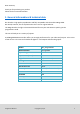
Dear customer, thank you for purchasing our product. Please find our instructions below. 1. General informations & technical data Our board is a high quality reproduction and fully compatible with the Arduino Mega 2560. We would, however, like to emphasize that this is not an original Arduino. The Mega board is the right microcontrollerboard for everyone who wants to quickly join the programmers world. This set will lead you to a variety of projects.
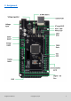
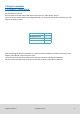
2. Assignment Ausgabe 19.05.
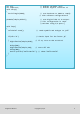
3. Software installation To start programming your JOY-IT ARD_Mega2560R3, you need to install the development environment, and, of course, the drivers, on your computer. The Arduino IDE is best for using with the Mega2560. It is licensed as open source software under the GPLv2 terms and ist concept and design is aiming for beginners. This IDE is completely compatible to our Mega2560R3 board and offers you every driver you need for a quick start. You can download the software here. 3.
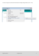
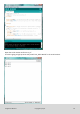
2. Choose the right port (marked with Arduino/Genuino Mega or Mega 2560) at [Tools -> Port]. Ausgabe 19.05.
4 EU-Declaration of conformity Manufacturer JOY-iT Europe GmbH Pascalstr. 8 47506 Neukirchen-Vluyn Article description: ard_mega2560R3 /ARD-Set01 Description: Microcontroller-Board / Set Purpose: experimental setup / prototyping The manufacturer, the JOY-IT Europe GmbH, Pascalstr.
5 Project examples 5.1 Project 1: „Hello World“ We start with an easy one. You just need the board and an USB cable to start with the „Hello World!“ project. This is an communication test for your Mega2560 and your computer and a basic project for your first steps in the Arduino world. Hardware Amount Mega2560 board USB cable LED 1 1 1 After completing the drivers installation, let‘s open the Arduino software and write some code, which displays „Hello World“ underneath your code.
int val; int ledpin=13; void setup() { Serial.begin(9600); pinMode(ledpin,OUTPUT); void loop() { val=Serial.read(); // defines variable “Val” // defines digital interface 13 // sets baudrate to 9600 to comply // with software configurationre // sets digital PIN 13 to output. // This configuration is requi //red when using I/O ports.
Open the serial monitor and insert a „R“. The LED is going to light up once and you will see „Hello World“ in the serial monitor. Ausgabe 19.05.
5.2 Project 2: flashing LED The flashing LED project is quite easy. We already discovered the LED in the previous project. This time we will connect the LED to a digital port. Diesmal werden wir eine LED mit einem der digitalen Pins verbinden. This is what we need: Hardware Amount Mega2560 board USB cable Red M5 LED 220Ω resistor Breadboard Breadboard cable 1 1 1 1 1 2 Just connect the components as seen in the circuit diagram below. We are going to use digital pin 10.
int ledPin = 10; void setup() { pinMode(ledPin, OUTPUT); // Defines digital PIN 10. // Defines PIN with connected LED as // output } void loop() { digitalWrite(ledPin, HIGH); delay(1000); digitalWrite(ledPin, LOW); delay(1000); } // // // // turns waits turns waits on LED a second off LED a second Nach dem Runterladen dieses Programms, wirst du im Experiment die an Pin 10 verbundene LED sich, mit einem Intervall von ca. einer Sekunde, Ein- und Ausschalten sehen. Ausgabe 19.05.
5.3 Project 3: PWM Lightcontrol PWM, short for Pulse Width Modulation, is a technique, used to translate analog signals into digital signals. A computer is not able to output an analog voltage. Er kann nur Digitalspannung ausgeben mit Werten wie 0V oder 5V. Therefore, a high-resolution counter is used, to code an analog signal level, by modulating the occupancy rate of PWM. The voltage and current is led by repeated pulse sequences to the component.
The three basic parameters of PWM: 1. Die amplitude of the pulse width (minimum/maximum) 2. Pulsefrequency 3. Voltage level The Mega2560 has 6 interfaces, supporting PWM: digital PIN 3, 5, 6, 9, 10 and 11. Mega2560 Platine USB Kabel Rote M5 LED Variabler Widerstand 220Ω Widerstand Amount In a previous project, we used a digital signal to control a LED. 1 Now we are going to use a potentiometer to adjust the 1 brightness of the LED.
While creating this program, we will make use of the analog writing function. In this experiment, we are going to read the analog value of the potentimeter and assign this value to the PWM port, to notice a change of LED brightness. The last part will be to show the analog value on the screen. Ausgabe 19.05.
int potpin=0; int ledpin=11; // initialises analog PIN 0 // initialises digital PIN 11 (PWM output) int val=0; void setup() { pinMode(ledpin,OUTPUT); Serial.begin(9600); // saves the value of the sensor // sets digital PIN 11 to output // sets baudrate to 9600 } void loop() { val=analogRead(potpin); Serial.
5.4. Projekt 4: Traffic lights We already discovered the flashing LED project. Now it is time to do a more complicated experiment: Traffic lights During this experiment we will used three LEDs with differecnt colors. Hardware Amount Mega2560 board USB cable Red M5 LED Yellow M5 LED Green M5 LED 1 1 1 1 1 220Ω resistor 3 Breadboard Breadboard cable 1 4 Ausgabe 19.05.
Because this is a simulation of traffic lights, the lighting duration should be as long as real traffic lights. Therefore we are going to use the Arduinos delayfunction, to control the delay. Ausgabe 19.05.
int redled =10; int yellowled =7; int greenled =4; void setup() { pinMode(redled, OUTPUT); pinMode(yellowled, OUTPUT); pinMode(greenled, OUTPUT); } void loop() { digitalWrite(greenled, HIGH); delay(5000); digitalWrite(greenled, LOW); for(int i=0;i<3;i++) { delay(5000); digitalWrite(yellowled, HIGH); delay(5000); digitalWrite(yellowled, LOW); } delay(5000); digitalWrite(redled, HIGH); delay(5000); digitalWrite(redled, LOW); } // initialises digital PIN 8 // initialises digital PIN 7 // initialises digital P
5.5 Project 5: LED Chase-Effect We often see billboards with colorful LEDs. These are always changing to form different effects. This experiment will simulate this effect. Hardware Amount Mega2560 board USB cable LED 1 1 6 220Ω resistor Breadboard Breadboard cable 6 1 12 Ausgabe 19.05.
int BASE = 2 ; // I/O PIN for the first LED int NUM = 6; // Amount of LEDs void setup() { for (int i = BASE; i < (BASE + NUM); i ++) { pinMode(i, OUTPUT); // sets I/O PINs to output } } void loop() { for (int i = BASE; i < (BASE + NUM); i ++) { digitalWrite(i, LOW); // sets I/O PIN to „low“, turns on LEDs // one after the other die LEDs delay(200); // delay } for (int i = BASE; i < (BASE + NUM); i ++) { digitalWrite(i, HIGH); // sets I/O PIN to „high“, // turns off LEDs one after the other delay(200); // de
5.6 Project 6: button-controled LED I/O Port is the interface for input and output. Until now we have just used the output. In this project we will try to use the input to read the value of the connected component. We will use a button and a LED with the input and output to give a better unterstanding of the I/O function. Buttons have a digital value. If the button is pressed, the circuit is closed and gets in a conductive state.
By pressing the button, the LED will light up. In this program, an if query is used.
5.7 Project 7: Responder experiment In this program are three buttons and one reset button which will control the three LEDs with 7 digital I/O PINs. Hardware Amount Mega2560 board USB cable Red M5 LED Yellow M5 LED Green M5 LED 220Ω resistor Buttons Breadboard 1 1 1 1 1 7 4 1 Breadboard cable 13 Ausgabe 19.05.
int redled=8; // sets red LED to „Output“ int yellowled=7; // sets yellow LED to „Output“ int greenled=6; // sets green LED to „Output“ int redpin=5; // initialises PIN for red button int yellowpin=4; // initialises PIN for yellow button int greenpin=3; // initialises PIN for green button int restpin=2; // initialises PIN for reset button int red; int yellow; int green; void setup() { pinMode(redled,OUTPUT); pinMode(yellowled,OUTPUT); pinMode(greenled,OUTPUT); pinMode(redpin,INPUT); pinMode(yellowpin,INPUT)
void YELLOW_YES() // executes the code until the yellow LED // is on. Ends the circle when the reset // button is pressed. { while(digitalRead(restpin)==1) { digitalWrite(redled,LOW); digitalWrite(greenled,LOW); digitalWrite(yellowled,HIGH); } clear_led(); } void GREEN_YES() // executes the code until the green LED // is on. Ends the circle when the reset // button is pressed.
5.8 Project 8: Active buzzer Active buzzers are used in computers, printers, alarm clocks, toys etc. to emit a sound. It has an inner vibration source. Connected to a 5V-Power-supply, it can buzz repeatedly. Hardware Amount Mega2560 board USB cable Buzzer Breadboard Breadboard cable 1 1 1 1 2 Ausgabe 19.05.
int buzzer=8; // initialises digital I/O PIN // to control the buzzer void setup() { pinMode(buzzer,OUTPUT); // sets pinmode to Output } void loop() { digitalWrite(buzzer, HIGH); } // makes sounds Das Projekt ist nach dem Übertragen des Programms abgeschlossen. Der Summer summt. Ausgabe 19.05.
5.9 Project 9: Passive buzzer With the Mega2560, many interactive projects are possible. The previous projects mainly dealt with LEDs but an often used project is the acoustic-optic display. Therefore, a passive buzzer is used which is, unlike the active buzzer, not able to activate itself. The activation occurs over a pulse frequency. Different frequencs result in different sounds. You can use this to play the melody of a song.
int buzzer=8; void setup() { pinMode(buzzer,OUTPUT); // sets buzzer Pin to output. } void loop() { unsigned char i,j; // defines variable while(1) { for(i=0;i<80;i++) // emits frequencysound { digitalWrite(buzzer,HIGH); // Sound delay(1); // 1ms delay digitalWrite(buzzer,LOW); // No sound delay(1); // 1ms delay } for(i=0;i<100;i++) // emits frequencysound { digitalWrite(buzzer,HIGH); // Sound digitalWrite(buzzer,LOW); // No Sound delay(2); // 2ms delay } } } Ausgabe 19.05.
5.10 Project 10: Reading analog values This project is about the analog interfaces of the Mega2560. An analogRead() command can the value of the interface. Because of the Analog-Digital-Converter of the Mega2560, the read-out values are between 0 and 1023. To be able to read the values, it is important to take care of the right baudrate. The baudrate of the computer has to meet the requirements of the device.
int potpin=0; int ledpin=13; int val=0; void setup() { pinMode(ledpin,OUTPUT); Serial.begin(9600); } void loop() { digitalWrite(ledpin,HIGH); delay(50); digitalWrite(ledpin,LOW); delay(50); val=analogRead(potpin); // initialises analog PIN 0 // initialises digital PIN 13 // defines „Val“ // sets digital PIN to „Output“ // sets Baudrate to 9600 // // // // // Serial.
5.11 Project 11: Light dependent resistor A light dependent resistor is a resistor which is changing its value by the incoming light. It is based on the photoelectric effect of semiconductors. If the incoming light is intensive, it reduces its power of resistance. If the incoming light is low, it raises its power of resistance. Light dependent resistors are usually used for light measurement, light control and for photovoltaic-conversion. We will use this effect to control the light intensity of a LED.
int potpin=0; // initialises analog PIN 0 an int ledpin=11; // initialises digital PIN 11. Ausgang int val=0; // initialises variable „Val“ void setup() { pinMode(ledpin,OUTPUT); // sets Pin 11 to output Serial.begin(9600); // sets baudrate to „9600“ } void loop() { val=analogRead(potpin); // reads analog value of the sensor Serial.println(val); // shows analog value in „Val“ analogWrite(ledpin,val); // turns on LED and sets brightness delay(10); // waits 0,01 seconds } Ausgabe 19.05.
5.12 Project 12: Flamesensor The Flamesensor (infrared receiving triode) is specially used by robots to find flamesources. This sensor has a high sensitivity to flames because infrared rays are very sensitive to fire. It has a specially build Infared-Receiverpipe to detect fire and convert the light of the flames to a signal. These signals are processed by the central processor. If the sensor is approaching a fire, the analog voltage is changing. If no fire is close, the voltage is by roughly 0.3V.
int flame=0; // int Beep=9; // int val=0; // void setup() { pinMode(Beep,OUTPUT); // pinMode(flame,INPUT); // Serial.begin(9600); // } void loop() { val=analogRead(flame); // Serial.println(val); // if(val>=600) // { digitalWrite(Beep,HIGH); }else { digitalWrite(Beep,LOW); } delay(500); } Ausgabe 19.05.
5.13 Project 13: Tilt switch We are going to use the tilt switch to control the on and off switch of a LED. The switch is on if the tilt switch is below a horizontal position. We can use the voltagevalue of the analog port, on which the tilt switch is connected to, to measure the position of the switch. Hardware Amount Mega2560 board USB cable Tilt switch 1 1 1 Red M5 LED 220Ω Resistor Breadboard 1 1 1 Breadboard cable 5 Ausgabe 19.05.
void setup() { pinMode(8,OUTPUT); // sets digital PIN 8 to „output“ } void loop() { int i; // defines variable i while(1) { i=analogRead(5); // reads the voltage value on analog PIN 5 if(i>512) // if higher then 512 (= 2.5V) { digitalWrite(8,LOW); // turn on LED } else // otherwise { digitalWrite(8,HIGH); // turn off LED } } } Wird das Breadboard bis zu einem bestimmten Grad geneigt, so schaltet sich die LED ein. Falls es keine Neigung gibt, bleibt die LED aus. Ausgabe 19.05.
5.14 Project 14: 1-digit LED segment display The LED segment displays are very common displays for numeric informations. They are often used in electric ovens, washing machines, water-temperature displays and electric clocks. The LED segment display is a semi-conductor and a light emitting devie. Its base-unit is a LED: The segment display can be devided in a 7-segement and a 8-segment display. The 8-segment display contains one more LED-unit (for the decimal dot).
Ausgabe 19.05.
// // // // // // // // // sets the IO PIN for every segment digital PIN 7 for segment a digital PIN 6 for segment b digital PIN 5 for segment c digital PIN 10 for segment d digital PIN 11 for segment e digital PIN 8 for segment f digital PIN 9 for segment g digital PIN 4 for segment dp // displays number 5 int a=7; int b=6; int c=5; int d=10; int e=11; int f=8; int g=9; int dp=4; void digital_0(void) { unsigned char j; digitalWrite(a,HIGH); digitalWrite(b,HIGH); digitalWrite(c,HIGH); digitalWrite(d,HIGH)
void digital_3(void) { digitalWrite(g,HIGH); digitalWrite(a,HIGH); digitalWrite(b,HIGH); digitalWrite(c,HIGH); digitalWrite(d,HIGH); digitalWrite(dp,LOW); digitalWrite(f,LOW); digitalWrite(e,LOW); } void digital_4(void) { digitalWrite(c,HIGH); digitalWrite(b,HIGH); digitalWrite(f,HIGH); digitalWrite(g,HIGH); digitalWrite(dp,LOW); digitalWrite(a,LOW); digitalWrite(e,LOW); digitalWrite(d,LOW); } void digital_5(void) { unsigned char j; digitalWrite(a,HIGH); digitalWrite(b, LOW); digitalWrite(c,HIGH); digitalWr
void digital_8(void) // displays number 8 { unsigned char j; for(j=5;j<=11;j++) digitalWrite(j,HIGH); digitalWrite(dp,LOW); } void digital_9(void) // displays number 9 { unsigned char j; digitalWrite(a,HIGH); digitalWrite(b,HIGH); digitalWrite(c,HIGH); digitalWrite(d,HIGH); digitalWrite(e, LOW); digitalWrite(f,HIGH); digitalWrite(g,HIGH); digitalWrite(dp,LOW); } void setup() { int i; // declares a Variable for(i=4;i<=11;i++) pinMode(i,OUTPUT); // sets PIN 4-11 to “output“ } void loop() { while(1) { digital_
5.15 Project 15: 4-digit LED segment display In this project we will use a 4-digit 7-segment LED display. Current limiting resistors are essential for LED displays. There are two ways of wiring the resistors. You can either connect one resistor to every anode (4 resistors connected to anode d1-d4) or you can connect one resistor to every PIN. The first way is needing less resistors but can not keep a constant display brightness. Ausgabe 19.05.
// PIN for anode int a = 1; int b = 2; int c = 3; int d = 4; int e = 5; int f = 6; int g = 7; int dp = 8; // PIN int d4 int d3 int d2 int d1 for cathode = 9; = 10; = 11; = 12; // sets variable long n = 1230; int x = 100; int del = 55; void setup() { pinMode(d1, OUTPUT); pinMode(d2, OUTPUT); pinMode(d3, OUTPUT); pinMode(d4, OUTPUT); pinMode(a, OUTPUT); pinMode(b, OUTPUT); pinMode(c, OUTPUT); pinMode(d, OUTPUT); pinMode(e, OUTPUT); pinMode(f, OUTPUT); pinMode(g, OUTPUT); pinMode(dp, OUTPUT); } void loop() {
void WeiXuan(unsigned char n)// { switch(n) { case 1: digitalWrite(d1,LOW); digitalWrite(d2, HIGH); digitalWrite(d3, HIGH); digitalWrite(d4, HIGH); break; case 2: digitalWrite(d1, HIGH); digitalWrite(d2, LOW); digitalWrite(d3, HIGH); digitalWrite(d4, HIGH); break; case 3: digitalWrite(d1,HIGH); digitalWrite(d2, HIGH); digitalWrite(d3, LOW); digitalWrite(d4, HIGH); break; case 4: digitalWrite(d1, HIGH); digitalWrite(d2, HIGH); digitalWrite(d3, HIGH); digitalWrite(d4, LOW); break; default : digitalWrite(d1, H
void Num_1() { digitalWrite(a, LOW); digitalWrite(b, HIGH); digitalWrite(c, HIGH); digitalWrite(d, LOW); digitalWrite(e, LOW); digitalWrite(f, LOW); digitalWrite(g, LOW); digitalWrite(dp,LOW); } void Num_2() { digitalWrite(a, HIGH); digitalWrite(b, HIGH); digitalWrite(c, LOW); digitalWrite(d, HIGH); digitalWrite(e, HIGH); digitalWrite(f, LOW); digitalWrite(g, HIGH); digitalWrite(dp,LOW); } void Num_3() { digitalWrite(a, HIGH); digitalWrite(b, HIGH); digitalWrite(c, HIGH); digitalWrite(d, HIGH); digitalWrite
void Num_5() { digitalWrite(a, HIGH); digitalWrite(b, LOW); digitalWrite(c, HIGH); digitalWrite(d, HIGH); digitalWrite(e, LOW); digitalWrite(f, HIGH); digitalWrite(g, HIGH); digitalWrite(dp,LOW); } void Num_6() { digitalWrite(a, HIGH); digitalWrite(b, LOW); digitalWrite(c, HIGH); digitalWrite(d, HIGH); digitalWrite(e, HIGH); digitalWrite(f, HIGH); digitalWrite(g, HIGH); digitalWrite(dp,LOW); } void Num_7() { digitalWrite(a, HIGH); digitalWrite(b, HIGH); digitalWrite(c, HIGH); digitalWrite(d, LOW); digitalWr
void Num_9() { digitalWrite(a, HIGH); digitalWrite(b, HIGH); digitalWrite(c, HIGH); digitalWrite(d, HIGH); digitalWrite(e, LOW); digitalWrite(f, HIGH); digitalWrite(g, HIGH); digitalWrite(dp,LOW); } void Clear() // clears screen { digitalWrite(a, LOW); digitalWrite(b, LOW); digitalWrite(c, LOW); digitalWrite(d, LOW); digitalWrite(e, LOW); digitalWrite(f, LOW); digitalWrite(g, LOW); digitalWrite(dp,LOW); } void pickNumber(unsigned char n) // pics number { switch(n) { case 0:Num_0(); break; case 1:Num_1(); br
void Display(unsigned char x, unsigned char Number) { WeiXuan(x); pickNumber(Number); delay(1); Clear() ; // clears screen } If the code above is fully transfered to the Mega2560, the display is showing “1234“. Ausgabe 19.05.
5.16 Project 16: LM35 Temperature-sensor The LM35 is an easy to use temperature sensor. You don‘t need any other hardware. The only difficulty is in writing the code which is calculating the readed analog values into celsius temperatures. Hardware Amount Mega2560 board USB cable LM35 Breadboard 1 1 1 1 Breadboard cable 5 Ausgabe 19.05.
int potPin = 0; void setup() { Serial.begin(9600); } void loop() { int val; int dat; val=analogRead(0); dat=(125*val)>>8; Serial.print("Temp:"); Serial.print(dat); Serial.
5.17 Project 17: 74HC595 The 74HC595 is a combination of a 8-digit shift register, flag and equipped with a tri-state output. We will use the 74HC595 to operate 8 LEDs in a resource-saving way. The needed I/O ports are reduced from 8 to 3 ports Hardware Amount Mega2560 board USB cable 74HC595 Chip Red M5 LED Green M5 LED 220Ω Resistor Breadboard Breadboard cable 1 1 1 4 4 8 1 37 Ausgabe 19.05.
int data = 2; // sets PIN 14 of the int clock = 5; // sets PIN 11 of the int latch = 4; // sets PIN 12 of the int ledState = 0; const int ON = HIGH; const int OFF = LOW; void setup() { pinMode(data, OUTPUT); pinMode(clock, OUTPUT); pinMode(latch, OUTPUT); } void loop() { for(int i = 0; i < 256; i++) { updateLEDs(i); delay(500); } } void updateLEDs(int value) { digitalWrite(latch, LOW); shiftOut(data, clock, MSBFIRST, ~value); digitalWrite(latch, HIGH); } Ausgabe 19.05.
5.18 Project 18: RGB LED This diode is controlled by PWM signals and contains a three-coloured system to display colors. The component can be connected directly to the ports of the Mega2560. Ausgabe 19.05.
int redpin = 11; int bluepin =10; int greenpin =9; // selects PIN for red LED // selects PIN for blue LED // selects PIN for green LED int val; void setup() { pinMode(redpin, OUTPUT); pinMode(bluepin, OUTPUT); pinMode(greenpin, OUTPUT); Serial.begin(9600); } void loop() { for(val=255; val>0; val--) { analogWrite(11, val); analogWrite(10, 255-val); analogWrite(9, 128-val); delay(1); } for(val=0; val<255; val++) { analogWrite(11, val); analogWrite(10, 255-val); analogWrite(9, 128-val); delay(1); } Serial.
5.19 Project 19: Infrared remote-control The IR-receiver converts the incoming light-signal into a low electric signal. To decode the remote-controls code it is necessary to know the coding method. The NEC-protocol is being used in this project. Hardware Amount Mega2560 board USB cable Infrared-receiver Infrared remote-control Red M5 LED 220Ω Resistor Breadboard Breadboard cable 1 1 1 1 6 6 1 11 Ausgabe 19.05.
Before transfering the code to the Mega2560, please install the IRremote library from the Arduino Library Manager. Otherwise the project is not going to work. Ausgabe 19.05.
#include
Serial.print(results->value, HEX); Serial.print(" ("); Serial.print(results->bits, DEC); Serial.println(" bits)"); } Serial.print("Raw ("); Serial.print(count, DEC); Serial.print("): "); for (int i = 0; i < count; i++) { if ((i % 2) == 1) { Serial.print(results->rawbuf[i]*USECPERTICK, DEC); } else { Serial.print(-(int)results->rawbuf[i]*USECPERTICK, DEC); } Serial.print(" "); } Serial.
void loop() { if (irrecv.decode(&results)) { if (millis() - last > 250) { on = !on; // digitalWrite(8, on ? HIGH : LOW); digitalWrite(13, on ? HIGH : LOW); dump(&results); } if (results.value == on1 ) digitalWrite(LED1, HIGH); if (results.value == off1 ) digitalWrite(LED1, LOW); if (results.value == on2 ) digitalWrite(LED2, HIGH); if (results.value == off2 ) digitalWrite(LED2, LOW); if (results.value == on3 ) digitalWrite(LED3, HIGH); if (results.value == off3 ) digitalWrite(LED3, LOW); if (results.
5.20 Project 20: 8x8 LED Matrix A 8x8 LED matrix contains 64 LEDs. Every single LED is placed in the intersection of row and column. The LED will light up If the level of the row is 1 and the level of the column is 0. For example: If you want to turn on the first LED, you have to turn PIN 9 to HIGH and PIN 13 to LOW. Ausgabe 19.05.
// setting up array to save the letters of 0 unsigned char Text[]={0x00,0x1c,0x22,0x22,0x22,0x22,0x22,0x1c}; void Draw_point(unsigned char x,unsigned char y) // show-dot function { clear_(); digitalWrite(x+2, HIGH); digitalWrite(y+10, LOW); delay(1); } void show_num(void) // Show-function calls show-dot function { unsigned char i,j,data; for(i=0;i<8;i++) { data=Text[i]; for(j=0;j<8;j++) { if(data & 0x01)Draw_point(j,i); data>>=1; } } } void setup(){ int i = 0 ; for(i=2;i<18;i++) { pinMode(i, OUTPUT); } clea