Jøtul F 3 CB Woodstove .................................... Installation and Operating Instructions for USA InstallationetfonctionnementpourCanada .................... Safety notice: If this solid fuel room heater is not properly installed, a house fire may result. For your safety, follow the installation directions. Contact local building or fire officials about restrictions and installation inspection requirements in your area. Kindly save these instructions for future reference.
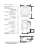
TABLE OF CONTENTS: 22 7/8 Standards and Safety Notices..........................3 Installations..........................................4 Chimney Requirements.............................6 Masonry Chimney.............6 Prefabricated Chimney.............6 Wall pass-throughs............7 Connecting to the Chimney.............................8 Masonry chimneys...............8 Hearthmount/Fireplaces...............9 Prefabricated Chimney...............9 Clearances.............................................
STANDARDS NOTICES The F 3 CB wood stove has been tested and listed to; · BE SURE TO READ THIS ENTIRE MANUAL BEFORE YOU INSTALL OR USE YOUR NEW JØTUL F 3 CB WOOD STOVE. U.S. Standards: ANSI/UL 737 and ANSI/UL 1482. Canadian Standards: CAN/ULC-S627-M93 · IF THIS ROOM HEATER IS NOT PROPERLY INSTALLED, A HOUSE FIRE MAY RESULT. TO REDUCE THE RISK OF FIRE, FOLLOW THE INSTALLATION INSTRUCTIONS. FAILURE TO FOLLOW THESE INSTRUCTIONS MAY RESULT IN PROPERTY DAMAGE, BODILY INJURY, OR EVEN DEATH.
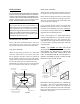
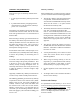
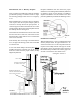
INSTALLATION REAR EXIT VENTING When rear exit venting is desired it will be necessary to knock-out the vent hole from the rear casting. IF THIS SOLID FUEL ROOM HEATER IS NOT PROPERLY INSTALLED A HOUSE FIRE MAY RESULT. FOR YOUR SAFETY, FOLLOW THE INSTALLATION DIRECTIONS. CONTACT THE LOCAL BUILDING OR FIRE OFFICIALS ABOUT RESTRICTIONS AND INSTALLATION INSPECTION REQUIREMENTS IN YOUR AREA. Remove the top casting of the stove by removing the two 3mm set screws that secures the top to the sides.
STOVE PIPE CHIMNEY CONNECTOR SIDE EXIT VENTING If venting through the side is desired it will be necessary to remove the top casting. Using a 3mm allen wrench remove the two set screws that secure to the top to the side panels. Remove the front door to avoid damage to the glass. Reminder: loss of the door washer will result in improper door alignment when reinstalling the door. The chimney connector is a single walled pipe used to connect the stove to the chimney.
CHIMNEY REQUIREMENTS Masonry Chimneys There are two types of chimneys suitable for the F 3 CB: When installing the F 3 CB into a masonry chimney you must conform to all of the following guidelines: 1. A code- approved masonry chimney with a flue liner. · The masonry chimney must have a fireclay liner or equivalent, with a minimum thickness of 5/8 and must be installed with refractory mortar. There must be at least ½ air space between the flue liner and chimney wall.
The manufacturers installation instructions must be followed precisely. Always maintain the proper clearance to combustibles as established by the pipe manufacturer. This clearance is usually a minimum of 2, although it may vary by manufacturer or for certain chimney components.
Consult your local building inspector, authorized Jøtul Dealer, NFPA 211 in the U.S. or CAN/CSA-B635 in Canada for other approved wall pass-through methods. CONNECTING TO THE CHIMNEY Masonry Chimney When installing a F 3 CB into a masonry chimney through a thimble(the opening through the chimney wall to the flue), the thimble must be lined with ceramic tile or metal and be securely cemented in place.
Hearth-mount into a Masonry Fireplace Fireplace installation must also observe the proper clearances to surrounding trim and mantels (addressed in clearance section of this manual). In addition, fireplace installations must also adhere to the floor protection guidelines specified in the following section. The F 3 CB may be installed into a masonry fireplace provided the opening is a minimum of 28 1/2 high. The short leg package reduces the stoves height by 2 1/4.
CLEARANCES TO COMBUSTIBLES Clearances to walls and ceilings Floor Protection The following clearances have been tested to UL and ULC standards and are the minimum clearances specifically established for the Jøtul F 3 CB. Floor protection under the F 3 CB woodstove, must be one of the following: 1. Any non combustible material with an insulative R value of 1.1. 2. Any UL, ULC or WH hearth board or prefrabricated non-combustible material.
F 3 CB WOODSTOVE CLEARANCES* STOVE CLEARANCES TOP VENT/VERTICAL UNPROTECTED SURFACES PROTECTED SURFACES per NFPA 211 or CAN/CSA-B365-M SIDE 24" 610 mm REAR 25" 635 mm CORNER SIDE 18" 10" 460 mm 255 mm REAR 14" 355 mm CORNER 10" 255 mm Rear heatshield with 18" Double wall pipe or shields 460 mm 10" 255 mm 14" 355 mm 6" 150 mm 6" 150 mm Rear heatshield with Single wall pipe STOVE CLEARANCES REAR VENT/HORIZONTAL 6" 150 mm UNPROTECTED SURFACES PROTECTED SURFACES per NFPA 211 or CAN/CSA-B365-M
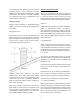
WALL SHIELDS FOR CLOSE CLEARANCE WALL SHIELD • • • • COMBUSTIBLE & WALL Must be 30” wide and centered behi nd the stove Must be 1” off the wall and 1” off the floor. With standard legs, the shield must be 32” high. With optional short legs, the shield must be 30” high. &20%867,%/( :$// WALL SHIELD • • • • Must be 1” off the wall and 1” off the floor. With standard legs, the shield must be 40” high. With optional short legs, the shield mus t be 38” high.
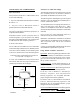
MINIMUM PROTECTED ALCOVE: NOTICE Accessories for woodstoves for clearance reduction have been developed by many manufacturers. If not following the methods of the installation codes, be sure that any accessory you choose has been tested by an independent laboratory and carries the laboratorys testing mark. Make sure to follow all of the manufacturers instructions. Assumestop exit, double wall pipe, and stoves rear heatshield.
WARNING: DO NOT INSTALL IN A BEDROOM/SLEEPING ROOM. THE STRUCTURAL INTEGRITY OF THE MOBILE HOMES FLOOR, WALL, CEILING/ROOF MUST BE MAINTAINED. OPERATION Before building a fire in your new F 3 CB, please read the following section carefully and completely. FIGURE 15 Do Not Burn First this stove is designed to burn natural wood ONLY, wood that has been air-dried for a period of 6 to 14 months will provide the cleanest most efficient heat.
Complete the following steps for the proper break-in procedure for the F 3 CB: 1. Light a small fire, newspaper and kindling only, only allow the stove to reach a maximum surface temperature of 200°. Burn for approximately 1 hour. 2. Allow stove to cool to room temperature. 3. Light a second fire, allowing the stove to reach a maximum temperature of 300° for 1 hour. 4. Cool the stove to room temperature. 5. Light a third fire and gradually allow the stove to reach a surface temperature of 400° 6.
(If you have at least a 2 thick ember bed when reloading, it may be possible to close the door and immediately adjust the air control setting). The Formation of Creosote When wood is burned slowly and at low temperatures, it produces tar and other organic vapors, which combine with moisture to form creosote. The slow moving smoke carries the creosote vapors, which condense in the cooler chimney flues, and this creosote then sticks to the chimney walls.
4. Remove all remaining debris from the glass area using a wire brush. 5. Apply a small bead of gasket/stove cement and the new gasket. Do not overlap the ends of the gasket rope. 6. Center the new glass panel over the gasket and reinstall the glass clips. See figure 17. IMPORTANT: The side of the glass treated with an infrared coating (marked on the perimeter) should always be facing outward.
ACCESSORIES MAINTENANCE LOG Many accessories have been manufactured for use with the Jøtul F 3 CB. ONLY USE ACCESSORIES THAT ARE SPECIFICALLY DESIGNED FOR THE JØTUL F 3 CB. DATE: SERVICE PERFORMED: Firescreen (part # 350168) The F 3 CB has been approved for use as an open fireplace, with front door open. This feature is especially nice when the ambience of a fire is desired. Some care should be taken when operating the stove as a fireplace.
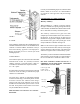
2B 2 22 15 62 59 57 6 52 55 7 51 12 11 8 46 31 26 24 22 29 45 19 42 35 64 65 73 70 76 EXPLODED VIEW OF THE F 3 CB
APPENDIX A: ALTERNATE FLOOR PROTECTION F 3 CB PARTS LIST 2 2B 6 7 8 11 12 15 22 23 24 26 28 29 31 35 37 40 42 43 45 46 51 52 55 57 59 62 64 65 70 76 73 78 79 Inner rear heatshield Outer rear heatshield Smoke outlet cover Traverse bar Top plate with smoke cover Baffle plate Air distributor Back plate Side plate Back burn plate Right burn plate Air deflector Sliding air vent Front plate Log retainer Door Hinge pin Start-up air vent Door handle complete Locking bar Glass Sparkscreen Ashlip Leg Bottom plate I
Stoves and fireplaces must be installed to conform to local and national building regulations. Before preparing for the installation of the appliance, it is important that the instructions issued with the unit are carefully read and strictly adhered to. Jøtul pursue a policy of constant product development. Products supplied may therefore differ in specification, colour and type of accessories from those illustrated and described in the brochure. Jøtul vise sans cesse à améliorer ses produits.