
User's Manual
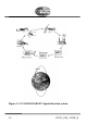
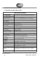
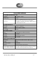
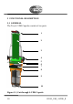
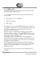
Table Of Contents
- 1 GENERAL DESCRIPTION
- 2 TECHNICAL SPECIFICATION
- 3 FUNCTIONAL DESCRIPTION
- 4 INSTALLATION
- 5 OPERATING INSTRUCTIONS
- 6 MAINTENANCE AND TROUBLESHOOTING
- 7 NOTES:
- 8 SERVICE AGENTS

82310_UM_ SVDR_E 19
1. Main EPIRB switch
2. Antenna board
3. Upper housing
4. Equator ring with gasket
5. EPIRB module
6. Recovery ring with mounting clips
7. S-VDR Server module
8. Lower housing
9. Battery module
10. S-VDR Connector
3.1.1 Capsule housing
The capsule module consists of upper and lower house mounted
together with an equator ring with gasket and locking pin.
3.1.2 S-VDR Server module
The S-VDR Server module consists of S-VDR Server module
house including Flash disc and a double-sided PCB board with
power regulator and PC circuits.
The S-VDR Server module is DC powered from the ship via the
bracket connector. The S-VDR data is fed from the ships S-VDR
system to the S-VDR Server module through the same connector.
When the capsule leaves the automatic release bracket, all
electrically power and data connections between the ship S-VDR
system and the S-VDR Server module inside the capsule is broken.