
User's Manual

DOC No: ZB7412-00A-DTS-R03
____________________________________________________________________________________
Copyright © JORJIN TECHNOLOGIES INC. 2017 25
http://WWW.JORJIN.COM.TW
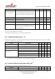
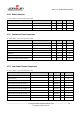
Hysteresis
<5
mV
Decision time
Step from –50 mV to +50 mV
<1
clock cycle
Current consumption when enabled
362
nA
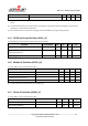
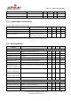
4.23. Programmable Current Source
Tc = 25°C, VDDS = 3.0 V, unless otherwise noted.
Parameter
Test Conditions
Min
Typ
Max
Units
Current source programmable output range
0.25-20
μA
Resolution
0.25
μA
Current consumption
(1)
Including current source at
maximum programmable output
23
μA
(1) Additionally, the bias module must be enabled when running in standby mode.
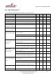
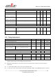
4.24. DC Characteristics
Parameter
Test Conditions
Min
Typ
Max
Units
TA = 25°C, VDDS = 1.8 V
GPIO VOH at 8-mA load
IOCURR = 2, high drive GPIOs only
1.32
1.54
V
GPIO VOL at 8-mA load
IOCURR = 2, high drive GPIOs only
0.26
0.32
V
GPIO VOH at 4-mA load
IOCURR = 1
1.32
1.58
V
GPIO VOL at 4-mA load
IOCURR = 1
0.21
0.32
V
GPIO pullup current
Input mode, pullup enabled, Vpad=0V
71.7
μA
GPIO pulldown current
Input mode, pulldown enabled, Vpad=VDDS
21.1
μA
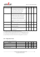
GPIO high/low input
transition, no hysteresis
IH = 0, transition between reading 0 and reading 1
0.88
V
GPIO low-to-high input
transition, with hysteresis
IH = 1, transition voltage for input read as 0→1
1.07
V
GPIO high-to-low input
transition, with hysteresis
IH = 1, transition voltage for input read as 1→0
0.74
V
GPIO input hysteresis
IH = 1, difference between 0→1 and 1→0 points
0.33
V
TA = 25°C, VDDS = 3.0 V
GPIO VOH at 8-mA load
IOCURR = 2, high drive GPIOs only
2.68
V
GPIO VOL at 8-mA load
IOCURR = 2, high drive GPIOs only
0.33
V
GPIO VOH at 4-mA load
IOCURR = 1
2.72
V
GPIO VOL at 4-mA load
IOCURR = 1
0.28
V