
User's Manual

Doc No: WG6611-00-DTS-D08
Copyright © JORJIN TECHNOLOGIES INC. 2017
http://WWW.JORJIN.COM.TW
CONFIDENTIAL
Page 6
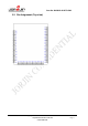
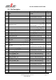
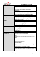
3.3. Pin Description
Pin#
Name
Description
Type
1
GND
Ground
G
2
GND
Ground
G
3
NC
Not Connected is not used
N
4
NC
Not Connected is not used
N
5
NC
Not Connected is not used
N
6
NC
Not Connected is not used
N
7
VDDIO(1.8~3.3V)
GPIOE, GPIOC, GPIOA, GPIOB
group IO power
P
8
NC
Not Connected is not used
N
9
SWCLK/GPIOE_4
Clock into the core
I/O
10
SWDIO/GPIOE_3
SWD data in/out
I/O
11
GPIOE_2/PWM2
GPIO Pin, PWM(multiplexing)
I/O
12
GPIOE_1/I2C2_SDA/PWM1
GPIO Pin, PWM, I2C(multiplexing)
I/O
13
GPIOE_0/I2C2_SCL
GPIO Pin, I2C(multiplexing)
I/O
14
NC
Not Connected is not used
N
15
ADC_CH2
ADC_CH2,AD converter input
I
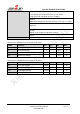
16
NC
Not Connected is not used
N
17
GND
Ground
G
18
CHIP_EN
1: Enable Chip
0: Disable chip in shutdown mode
I
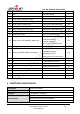
19
NC
Not Connected is not used
N
20
NC
Not Connected is not used
N
21
NC
Not Connected is not used
N
22
GPIOA_3/UART0_RTS
GPIO Pin, UART(multiplexing)
I/O
23
NC
Not Connected is not used
N
24
GPIOA_5/UART0_CTS
GPIO Pin, UART(multiplexing)
I/O
25
GPIOA_7/UART0_TXD
GPIO Pin, UART(multiplexing)
I/O
26
GPIOA_6/UART0_RXD
GPIO Pin, UART(multiplexing)
I/O
27
GND
Ground
G
28
NC
Not Connected is not used
N
29
NC
Not Connected is not used
N
30
GND
Ground
G
31
NC
Not Connected is not used
N
32
NC
Not Connected is not used
N