
User's Manual

Doc No: WG1300BE00 EM Board-UG-R02
Copyright © JORJIN TECHNOLOGIES INC. 2014
http://WWW.JORJIN.COM.TW
CONFIDENTIAL
Page 18
4. LAYOUT GUIDELINES
4.1. Board Layout
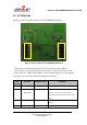
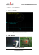
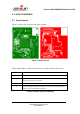
Figure 9 shows the 2 layers evaluation board.
Figure 9. Board Layout
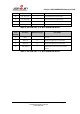
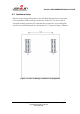
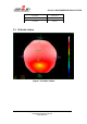
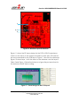
Table 8 and Figure 10 describe instances of good layout practices.
Reference
Guideline Descriptions
1
The proximity of ground vias must be close to the pad.
2
Signal traces must not be run underneath the module on the layer
where the module is mounted.
3
Increase the ground pour in the first layer.
4
Have a solid ground plane and ground vias under the module for
stable system and thermal dissipation.
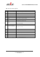
Table 8. Module Layout Guidelines