Operator’s manual (EPA) Please read the operator’s manual carefully and make sure you understand the instructions before using the machine.
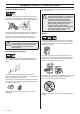
KEY TO SYMBOLS Symbols WARNING! Clearing saws, brushcutters and trimmers can be dangerous! Careless or incorrect use can result in serious or fatal injury to the operator or others. It is extremely important that you read and understand the contents of the operator’s manual. Only intended for trimmer heads. Other symbols/decals on the machine refer to special certification requirements for certain markets.
CONTENTS Contents KEY TO SYMBOLS Symbols ....................................................................... CONTENTS Contents ...................................................................... Note the following before starting: ................................ INTRODUCTION Dear customer! ............................................................ WHAT IS WHAT? What is what? .............................................................. GENERAL SAFETY PRECAUTIONS Impor tant .......................
INTRODUCTION Dear customer! Congratulations on your choice to buy a Jonsered product! Your purchase gives you access to professional help with repairs and service whenever this may be necessary. If the retailer who sells your machine is not one of our authorized dealers, ask for the address of your nearest servicing dealer. It is our wish that you will be satisfied with your product and that it will be your companion for a long time. Think of this operator′s manual as a valuable document.
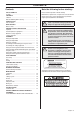
WHAT IS WHAT? GC2125C 30 31 What is what? 1 Trimmer head 17 Locking nut 2 Grease filler cap, bevel gear 18 Support flange 3 Bevel gear 19 Drive disc 4 Cutting attachment guard 20 Socket spanner 5 Shaft 21 Operator’s manual 6 Loop handle 22 Locking pin 7 Throttle control 23 Allen key 8 Stop switch 24 Support cup 9 Throttle lockout 25 Blade 10 Cylinder cover 26 Transport guard 11 Starter handle 27 J-handle 12 Fuel tank 28 Support eyes for harness 13 Choke control 29 Harnes
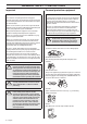
GENERAL SAFETY PRECAUTIONS Important Personal protective equipment IMPORTANT! IMPORTANT! The machine is only designed for trimming grass. A clearing saw, brushcutter or trimmer can be dangerous if used incorrectly or carelessly, and can cause serious or fatal injury to the operator or others. It is extremely important that you read and understand the contents of this operator’s manual.
GENERAL SAFETY PRECAUTIONS CLOTHING Wear clothes made of a strong fabric and avoid loose clothing that can catch on twigs and branches. Always wear heavy, long pants. Do not wear jewellery, shorts sandals or go barefoot. Secure hair so it is above shoulder level. Make sure the throttle control is locked at the idle setting when the throttle lockout is released. FIRST AID KIT Always have a first aid kit nearby.
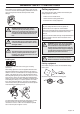
GENERAL SAFETY PRECAUTIONS Cutting attachment guard This guard is intended to prevent loose objects from being thrown towards the operator. The guard also protects the operator from accidental contact with the cutting attachment. Check that the guard is undamaged and not cracked. Replace the guard if it has been exposed to impact or is cracked. Check that the vibration damping element is undamaged and securely attached.
GENERAL SAFETY PRECAUTIONS If the muffler on your machine is fitted with a spark arrestor screen this must be cleaned regularly. A blocked screen will cause the engine to overheat and may lead to serious damage. Cutting equipment This section describes how to choose and maintain your cutting equipment in order to: • Reduce the risk of blade thrust. • Obtain maximum cutting performance. • Extend the life of cutting equipment.
GENERAL SAFETY PRECAUTIONS General rules Trimmer head IMPORTANT! Always ensure the trimmer cord is wound tightly and evenly around the drum, otherwise the machine will generate harmful vibration. Only use cutting attachments with the guards we recommend! See the chapter on Technical data. • Only use the recommended trimmer heads and trimmer cords. These have been tested by the manufacturer to suit a particular engine size. This is especially important when a fully automatic trimmer head is used.
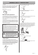
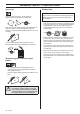
ASSEMBLY Fitting the loop handle Fitting the J-handle (GT 2125) (GC 2125, GC 2125C) • Position the handle on the shaft. Note that the handle must be mounted below the arrow on the shaft. • Clip the loop handle onto the shaft. Note that the loop handle must be fitted between the arrows on the shaft. • Fit the screw, securing plate and wing nut as shown in the diagram. • Slide the spacer into the slot in the loop handle. • Tighten the wing nut. • Fit the nut, knob and screw. Do not overtighten.
ASSEMBLY Assembling and dismantling the two-piece shaft Assembling the cutting equipment (GC 2125C) ! Assembly: • Loosen the coupling by turning the knob. • Align the tab of the attachment (A) with the arrow on the coupling (B). WARNING! When fitting the cutting attachment it is extremely important that the raised section on the drive disc/support flange engages correctly in the centre hole of the cutting attachment.
ASSEMBLY • Insert a finger into the centre hole of the cover (I) while grasping the cover with your other fingers. Using the index finger and thumb of your other hand, release the two catches (J) that engage in the cut-outs in the bottom half (K). Pull apart the trimmer head, grasping the cover firmly. • Place the cover (I) and the support flange (F) on the output shaft. • Fit the nut (G). The nut must be tightened to a torque of 35-50 Nm (3.5-5 kpm). Use the socket spanner in the tool kit.
ASSEMBLY Fitting the trimmer guard and trimmer head (GT 2125) Guard • Fit the guard as shown in the diagram. Tighten securely. Trimmer head • Fit the dust cup on the shaft. The nut must be completely covered by the dust cup. • Hold the dust cup with a spanner to prevent the shaft from rotating. • Screw the trimmer head onto the shaft.
FUEL HANDLING Fuel safety Gasoline Never start the machine: 1 If you have spilled fuel on it. Wipe off the spillage and allow remaining fuel to evaporate. 2 If you have spilled fuel on yourself or your clothes, change your clothes. Wash any part of your body that has come in contact with fuel. Use soap and water. 3 If the machine is leaking fuel. Check regularly for leaks from the fuel cap and fuel lines.
FUEL HANDLING Mixing • Always mix the gasoline and oil in a clean container intended for fuel. • Always start by filling half the amount of the gasoline to be used. Then add the entire amount of oil. Mix (shake) the fuel mixture. Add the remaining amount of gasoline. • Fueling ! Mix (shake) the fuel mixture thoroughly before filling the machine’s fuel tank. WARNING! Taking the following precautions, will lessen the risk of fire: Do not smoke or place hot objects near fuel.
STARTING AND STOPPING Check before starting • Check the blade to ensure that no cracks have formed at the bottom of the teeth or by the centre hole. The most common reason why cracks are formed is that sharp corners have been formed at the bottom of the teeth while sharpening or that the blade has been used with dull teeth. Discard a blade if cracks are found.
STARTING AND STOPPING CAUTION! Do not pull the starter cord all the way out and do not let go of the starter handle when the cord is fully extended. This can damage the machine. CAUTION! Do not put any part of your body in marked area. Contact can result in burns to the skin, or electrical shock if the spark plug cap has been damaged. Always use gloves. Do not use a machine with damaged spark plug cap. Stopping The engine is switched off by moving the stop switch to the stop position.
WORKING TECHNIQUES General working instructions 6 Always hold the machine with both hands. Hold the machine on the right side of your body. 7 Keep the cutting attachment below waist level. 8 Switch off the engine before moving to another area. Fit the transport guard before carrying or transporting the equipment any distance. 9 Never put the machine down with the engine running unless you have it in clear sight.
WORKING TECHNIQUES ! WARNING! Machines fitted with saw blades or grass blades can be thrown violently to the side when the blade comes into contact with a fixed object. This is called blade thrust. A blade thrust can be violent enough to cause the machine and/or operator to be propelled in any direction, and possibly lose control of the machine. Blade thrust can occur without warning if the machine snags, stalls or binds.
WORKING TECHNIQUES Sweeping • The fan effect of the rotating cord can be used for quick and easy clearing up. Hold the cord parallel to and above the area to be swept and move the tool to and fro. • When cutting and sweeping you should use full throttle to obtain the best results.
MAINTENANCE Carburetor Basic setting Your Jonsered product has been designed and manufactured to specifications that reduce harmful exhaust fumes. The engine will be run in after it has used 8-10 tanks of fuel. To ensure that the engine runs at peak performance and produces as little harmful exhaust fumes as possible after the running-in period, ask your dealer/service workshop (which has a rev counter for this purpose) to adjust your carburettor.
MAINTENANCE Fine adjustment of the idle speed T Correctly adjusted carburetor Adjust the idle speed using the idle adjustment screw T, if it is necessary to readjust. First turn the idle adjustment screw T clockwise until the cutting attachment starts to rotate. Then turn the screw anticlockwise until the cutting attachment stops. The idle speed is correctly adjusted when the engine will run smoothly in every position.
MAINTENANCE Cooling system Oiling the air filter To keep the working temperature as low as possible the machine is equipped with a cooling system. Always use special filter oil. Filter oil contains a solvent to make it spread evenly through the filter. You should therefore avoid skin contact. The cooling system consists of: 1 Air intake on the starter. 2 Fins on the flywheel. 3 Cooling fins on the cylinder. 4 Cylinder cover (directs cold air over the cylinder).
MAINTENANCE Two-piece shaft (GC 2125C) The drive shaft end in the lower shaft should be lubricated with grease every 30 hours. There is a risk that the drive shaft ends (splined coupling) on models with two-piece shafts will seize if they are not lubricated regularly. Bevel gear The bevel gear is filled with the right amount of grease at the factory. However, before using the machine you should check that the bevel gear is filled 3/4 full with grease. Use JONSERED special grease.
MAINTENANCE Maintenance schedule The following is a list of the maintenance that must be performed on the machine. Most of the items are described in the Maintenance section. The user must only carry out the maintenance and service work described in this manual. More extensive work must be carried out by an authorised service workshop. Maintenance Daily maintenance Clean the outside of the machine. X Check that the harness is not damaged.
TECHNICAL DATA Technical data Technical data GT 2125 GC 2125 GC 2125C Cylinder displacement, cu.in/cm3 1,50/24,5 1,50/24,5 1,50/24,5 Cylinder bore, inch/mm 1,26/32 1,26/32 1,26/32 Stroke, inch/mm 1,06/27 1,06/27 1,06/27 Idle speed, rpm 2700 2700 2700 Recommended max. speed, rpm 11000-11700 11000-11700 10000-10500 Speed of output shaft, rpm 11700 8014 8014 Max. engine output, acc.
TECHNICAL DATA The accessories are recommended for use in combination with the specified power heads and have been evaluated to applicable ISO- and EN safety requirement standards by the Swedish Machinery Testing Institute. Powerhead model GC 2125C Accessories Art No.
FEDERAL EMISSION CONTROL WARRANTY STATEMENT YOUR WARRANTY RIGHTS AND OBLIGATIONS rights and responsibilities, you should contact your nearest authorized servicing dealer or call Jonsered, at Sweden +4636-146500. The EPA (The US Environmental Protection Agency), Environment Canada and Jonsered are pleased to explain the emissions control system warranty on your 2001 and later small nonroad engine. In U.S.
Tap-N-Go 25 2 3 2,0-2,4 mm .079-.
Trimmy H II 1 2 3 4 2,0-2,4 mm .080-.
S35 2 3 2,4-2,7 mm .095-.
S35 3 2 2,4-2,7 mm .095-.
Tap-N-Go 35 2 3 2,4-2,7 mm .095-.
Auto 32 1 2 3 4 2,4 mm .
1150271-95 ´®z+R;3¶5y¨ ´®z+R;3¶5y¨ 2007-01-25