
User Manual


www.joinwit.com
10
frequency with the power range more than -20dBm.
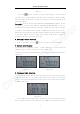
6.Power meter calibration mode
In the power meter mode,press“ ”and“ ”, at the same time, “U-01”will
appear on the screen top right corner, indicating that the meter has come to power value
calibration mode. Press “ ”and “ ” to increase or decrease the absolute
optical power value. When the adjusted value is what you need, you can press “ ”
to save the current calibration value. After “----”appears on the screen, it means
the calibration is ok and then press “ ”to exit.(image 5-15)
Image 5-15
For example:take the 1310 wavelength calibration for an example:
① Select a high-stability 1310nm source, and then connect it to one end of patch
cord. The other end of the patch cord is inserted to the detecting port of the standard
power meter and tightens it. Choose 1310nm wavelength in the standard power meter,
and read the absolute optical power value, for example, we can set it for A.
② Removed from the detecting port of the standard optical power meter, patch cord
is inserted to the detecting port of the calibrated instrument power meter. Then
change the wavelength in the calibrated optical power meter to 1310nm. Press
“ ”and “ ” to increase or decrease the absolute optical power value
displayed on the calibrated instrument screen. When the absolute optical power value
on the calibrated instrument is A, press“ ” to save the current calibration
value. “----” on the screen indicates that the calibration is done.
③ Other wavelength calibration is just like 1310nm wavelength, after calibration,
press“ ” to exit.
Note:All the meters have a rigorous calibration check in the factory. So the users
are better not to use this function to avoid the meter measurement deviation!
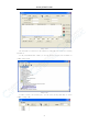
7. Date communication
Note:Before data communications, make sure the drivers and application software