User Manual EDI-120 Control Retrofit for Electronics Diversified Inc. (EDI) Mark VII Dimmer Racks JOHNSON SYSTEMS INC. www.johnsonsystems.
Contents Warranty...........................................................................................................2 Introduction.......................................................................................................3 Packaging & Contents......................................................................................4 Dimensional Drawings......................................................................................4 Installation.........................................
Introduction The EDI-120 is a next generation retrofit electronics package designed specifically for upgrading the EDI Mark VII performance dimmer racks making system replacement completely unnecessary. This full-featured, ETL approved, state-of-the-art unit provides a direct digital interface to most of today’s modern lighting communication protocols.
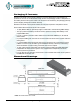
Packaging & Contents Each EDI-120 retrofit control system is shipped in a custom designed box and packaging for protection of the unit. It’s recommended to keep the box and packaging stored in a safe place. In the unlikely event that the system needs to be returned to the JSI Factory, the packaging will help prevent shipping damage and maintain warranty. Each EDI-120 retrofit control system includes all of the parts required to complete the retrofit.
Installation • Disconnect (turn off) the power supply to the EDI Mark VII dimmer rack(s). WARNING! Verify all power is disconnected (turned off) before proceeding. Removal of the old EDI Control Module • Remove the four (4) mounting screws securing the EDI Mark VII control module. • Carefully pull the control module forward until all of the rear wiring connections are visible. Do not disconnect any wiring at this point.
• Disconnect the P1 power connector/cable. Carefully squeeze the latches on each side of the connector together to release the connector and then pull the connector out. Inspect the connector and the termination of the wires in the connector. Be sure everything looks okay. • Disconnect the P2 connector/cable.
• • • • • • If more than four (4) analog inputs are required, additional equipment may be necessary to facilitate them. Consult the factory for options and further information. Dress out and terminate any applicable connections for the input/output contacts on the breakaway connector provided. Dress out and terminate any applicable +12VDC power supply connections on the breakaway connector provided.
• Ensure chassis is connected to earth ground. POWER SUPPLY INPUT 120/208VAC, 3P4W, 1.3A, 60Hz 120/240VAC, 1P3W, 1.3A, 60Hz EXTERNAL DISCONNECT REQUIRED P1 • • • • • • • • • • • • • • 8 If the connector needs to be moved, follow the following procedure: First, remove the ten (10) #4-40 x 1/4” mounting screws that fasten the lid onto the EDI-120 chassis. Remove the lid and set it aside, along with the screws.
Turn on and test the new EDI-120 Retrofit System • Connect (turn on) the power supply to the EDI Mark VII dimmer rack. • Verify the operation of the system status LED indicators, LCD display and programming switches. • Refer to the programming section of this manual for system configuration. • Test the system thoroughly to ensure all wiring terminations are functioning. • Verify all of the dimmer control outputs have the correct phase referencing.
OEM Connector Pinouts OEM P3, P4, P5 and P6 Dimmer (PWM) Control Cable Pinout PIN 1 2 3 4 5 6 7 8 9 10 11 12 13 14 15 16 17 18 19 20 21 22 23 24 25 26 27 28 29 30 31 32 33 34 35 36 37 38 39 40 41 42 43 44 45 46 47 48 49 50 P3 Connector FUNCTION Dimmer (PWM) 1 Dimmer (PWM) 2 Dimmer (PWM) 3 Dimmer (PWM) 4 Dimmer (PWM) 5 Dimmer (PWM) 6 Dimmer (PWM) 7 Dimmer (PWM) 8 Dimmer (PWM) 9 Dimmer (PWM) 10 Dimmer (PWM) 11 Dimmer (PWM) 12 Dimmer SSR +12VDC Dimmer Overtemp DC Common DC Common Dimmer (PWM) 13 Dimmer (PWM)
Control Input/Output Connections DMX-A AND DMX-B INPUT AND THRU DAISY-CHAIN MULTIRACK INSTALLATIONS All EDI-120 retrofit control systems come with a variety of control input and output (I/O) capabilities. All I/O connections are terminated on the connectors located at the rear of the EDI-120 chassis. Breakaway type connectors are provided for all I/O connections. • • • • Use wire size #28 to #12 AWG. Strip wire insulation length to 0.28” (7mm). Use a 1/8” (3.
+12V Common +12V Analog Input 1 Thru 4 Common +12V Maintained Normally Open Switch Contact Analog Input 1 Thru 4 Overtemp Input Normally Open Normally Open Thermostat Switch Common Fire Alarm Input Maintained Normally Open Switch Contact Common Security Alarm Input Maintained Normally Open Switch Contact Common Auxiliary Input Maintained Normally Open Switch Contact Common +12V 100mA Max Open Collector Output 12 +12VDC Power Supply Output • A regulated +12VDC power supply is available for
EEPROM Memory Module EEPROM Memory Module All EDI-120 retrofit control systems come equipped with a removable EEPROM memory module located at the rear of the EDI-120 chassis. The EEPROM memory module inserts into the on-board connector located at the rear of the EDI-120 chassis. The EEPROM memory module is primarily used to backup important configuration settings, and may be removed for safe storage. If a firmware update is required, Johnson Systems Inc.
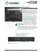
User Interface Programming Switches LCD Display Infrared LED System Status LED Indicators EDI-120 retrofit control systems are equipped with a user interface. The user interface provides access to all programming and configuration settings. System status is easily visible on the LCD display and LED indicators. An infrared LED allows for printout of all system configuration settings when used with a hand held infrared printer (Johnson System Inc., Part Number: JS-IP).
System Status • LED Indicators RUN (Green) Illuminates when the power is on and the microcontroller status is in normal run mode. The LED flashes once every 2 seconds when the system is in STANDBY mode. ØA, ØB and ØC (Green) Illuminates when the line voltage power is within the acceptable range of 100-130 VAC for each phase and the zero-cross reference circuitry is functioning properly.
INF HOLD Displayed when DMX is disconnected and the systems predetermined DMX status hold (SH) time is set for infinite (INF) hold. Refer to menu item “SH TIME” on page 23 for further details. SCENE:XX Displays the scene (1 to 12) that is currently activated. The colon in front of the scene number flashed twice per second during fading. Refer to menu item “SCENEMOD” on page 26 for further details. A-SCENE! Displayed when the auxiliary input is triggered.
Quick Programming Reference 1. SCENESET 2. FADETIME 3. SNAPSHOT 4. DIM TEST 5. MONITOR 6. ADDRESS 7. DMX MODE 8. 2 RM SET 9. DMXA TRM 10. DMXB TRM 11. DMX O/P 12. DMXA PAT 13. DMXB PAT 14. SH TIME 15. DC PATCH 16. DIM CURV 17. VOUT LIM 18. REGULATE 19. ANA MODE 20. ANA PAT 21. ANA TEST 22. ANA FLTR 23. ANA BLOC 24. STANDBY 25. TEST INC 26. OC MODE 27. AUX IN 28. SCENEMOD 29. S-ALARM 30. F-ALARM 31. Ø-PATCH 32. WARMING 33. LINE V 34. LINE F 35.
Detailed Programming of System Configuration Menu Items NOTE: The programming switches can be locked out to prevent inadvertent configuration changes. To toggle between “LOCKED!!” and “UNLOCKED” press and hold down the EXECUTE and then ESCAPE switches at the same time for 4-5 seconds. The sequence of the following system configuration menu items appear as the MENU DOWN ( ) switch is pressed. Pressing the MENU UP ( ) switch will sequence the system configuration menu items in the opposite order.
2. FADETIME S>01T 05 S>12T 05 S 12T>05 S 12T>99 Set the fade time for each of the 12 scenes from 0 to 99 seconds. The factory default is 5 seconds for all 12 presets. Press EXECUTE to enter the menu. Displays the scene (S>01) and assigned fade time (T 05). Press MENU ( ) to select a different scene from 01 to 12. Press EXECUTE to toggle between scene (S>) and fade time (T>) selection. Press MENU ( ) to select a different fade time from 00 to 99 seconds.
6. ADDRESS DMXA>001 DMXA>512 DMXA>001 DMXB>001 DMXB>512 #CHA=001 #CHA=120 The DMX start address can be assigned from 001 to 512 and is common to both DMX inputs. When DMX MODE is set for DMX A+B operation, each of the DMX inputs can be assigned to a separate DMX start address. The DMX inputs are merged and DMX-B is offset by the number of DMX-A channels. Press EXECUTE to enter the menu. Displays the current DMX start address for the DMX A input.
8. 2 RM SET D 001 A D 120 A D 120 B Set the two room assignment for each of the dimmer outputs. This menu is used to assign each of the 120 dimmer outputs to room “A” or room “B”. Dimmer outputs assigned to room “A” are controlled via the DMX-A input. Dimmer outputs assigned to room “B” are controlled via the DMX-B input. This creates separation within the dimmer rack and makes a single dimmer rack function as though it is two independent dimmer racks.
DISABLED ENABLED OFFSET PATCH Press EXECUTE to enter the menu and configure the DMX mode. This menu is disabled to help prevent inadvertent changes. Proceed to enable. Press and hold MENU ( ) and MENU ( ) at the same time for 4-5 seconds. Press EXECUTE to toggle the DMX mode from OFFSET to PATCH. Press EXECUTE to toggle the DMX mode from PATCH to OFFSET. Press ESCAPE or RESET to exit the menu. Any change in the configuration is automatically saved. 12.
DIM#:001 DIM#:120 DIM#:001 DMXA:001 DMXA:512 DMXA:001 #DIM:001 #DIM:120 #DIM:001 PROCEED? SURE ??? DONE !!! CLEAR? SURE ??? DONE !!! Press EXECUTE to select the first dimmer number (DIM#) in the block. Press MENU ( ) to edit the dimmer number (DIM#) from 001 to 120. Press MENU ( ) and MENU ( ) at the same time to toggle back to 001. Press EXECUTE to select the DMX A (DMXA) start address for the block.
16. DIM CURV D 001 SQ D 120 SQ D 120 LN D 120 DD D 120 ND Configure the dimmer curve for each output. There are four different dimmer curve profiles that can be assigned to each individual dimmer output circuit. Square Law (SQ) curve is the industry standard and the default for all dimmers. Linear (LN) curve modifies the dimmer output for a linear relationship to the control input level.
20. ANA PAT A01C001 A04C001 A04C001 A04C001 A04C120 A04C120* A04C120* Patch the analog inputs to any combination of control channels. Press EXECUTE to enter the menu and activate analog patch mode. Displays the active analog (A) input and control channel (C). Press MENU ( ) to select the desired analog input to patch from 01 to 04. Press EXECUTE to toggle from analog (A) to channel (C) selection. The cursor (_) position indicates analog (A) or channel (C) selection.
25. TEST INC PERCENT HEX VAL 26. OC MODE A+D< 001 A+D> 001 A+D> 512 A+D< 512 DMX< 512 ANA< OFF< 27. AUX IN SCENE:01 SCENE>01 SCENE>12 28. SCENEMOD ENABLED DISABLED 26 Set the test increment units to percent or hexadecimal. The levels for the dimmer test (DIM TEST) and analog test (ANA TEST) features can be displayed as a percentage or hexadecimal value.
29. S-ALARM LFLC001* L00C001* LFLC001* LFLC001* LFLC001* LFLC120* LFLC120 LFLC120* LFLC120* 30. F-ALARM LFLC001* L00C001* LFLC001* LFLC001* LFLC001* LFLC120* LFLC120 LFLC120* LFLC120* 31. Ø-PATCH C 001 ØA C 120 ØC C 120 ØA Select the level and control channels triggered by the security alarm input.
C 120 ØB C 120 ØC Press EXECUTE to toggle the patch to Phase B (ØB). Press EXECUTE to toggle the patch to Phase C (ØC). Press ESCAPE to exit the menu and save the desired settings. Press RESET to exit the menu without saving. The menu will automatically timeout after 5 minutes of inactivity and save. 32. WARMING DISABLED ENABLED ON OFF Turn the “lamp warming” feature on or off.
K:XXXXXX K:XXXXXX K:XXXXXX K>XXXXXX K>XXXXXX K:>XXXXX K:>XXXXX K:X>XXXX K:X>XXXX K:XX>XXX K:XX>XXX K:XXX>XX K:XXX>XX K:XXXX>X K:XXXX>X Shows the unique six-character hard-key code (XXXXXX). Follow the procedure below to enter the menu and modify the hard-key. Press and hold EXECUTE and then ESCAPE at the same time for 4-5 seconds. A pointer (>) appears to indicate hard-key modification is activated.
MEMCHECK CRC-TEST >>>>>>>> VER X.X UPDATE?? SURE ??? UPDATING WILL AUTO RESTART PLEASE WAIT.... NO MEM! WRONG MEM TYPE WRONG PRODUCT CRC ERR! 42. RESTORE DISABLED ENABLED MEMCHECK OKAY....
43. BACKUP DISABLED ENABLED MEMCHECK SURE ??? WAIT VERIFY DONE!! NO MEM! WRONG MEM TYPE WRONG PRODUCT DATA ERR Backup parameters and save them in the EEPROM memory module. All of the configuration setting parameters can be saved in the EEPROM memory module for backup. The backup parameters can then be restored if they have been inadvertently changed or corrupted. Once backup is complete the EEPROM memory module may be removed for safe storage.
45. DEFAULTS ØPATCH1? ØPATCH2? CURVES? ANA-OFF? V-LIMIT? DCPATCH? FD-TIME? 2 ROOM? SURE??? DONE!!! Set various system configuration settings to the factory default. Press EXECUTE to enter the menu. Press MENU ( ) to scroll through and select which item(s) to default. Sets the dimmer phase patch to AABBCC. This is the default setting. Sets the dimmer phase patch to AAAAAA. Sets all 120 dimmer curve profiles to Square Law curve.
Important Hard-key Information EDI-120 retrofit control systems may be shipped with an invalid hard-key code of 000000. A valid hard-key must be entered before the run time (RTIME) counter reaches 2,160 hours / 90 days. If the run time expires without a valid hard-key, the LCD display will show a runtime counter error (RTC ERR!) and all dimmer control outputs will be disabled. Refer to menu item “HARD-KEY” on page 28 of the user manual for detailed instructions on how to enter a valid hard-key code.
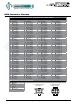
Troubleshooting Reference This manual is accurate at time of printing and subject to revisions and technical updates as required without prior notice. Please visit www.johnsonsystems.com for applicable updates. 34 www.johnsonsystems.
Troubleshooting Reference This manual is accurate at time of printing and subject to revisions and technical updates as required without prior notice. Please visit www.johnsonsystems.com for applicable updates. www.johnsonsystems.
User Manual EDI-120 Series Control Retrofit for Electronics Diversified Inc. (EDI) Mark VII Dimmer Racks Rev. 2 www.johnsonsystems.