
Manual
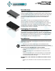
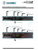
Table Of Contents
- Warranty
- Introduction
- Packaging & Contents
- Installation
- DPC-24/12 Circuit Board
- DPC-12 and DPC-24 Control Module Face Panels
- Dual DMX Input and Thru Connectors
- User Interface
- LCD Display
- Programming Switches
- 12 or 24 Local Buttons/Switches
- System Status - LED Indicators
- System Status - LCD Display
- Quick Programming Reference to System Configuration Menu Items
- Detailed Programming of System Configuration Menu Items
- Troubleshooting Reference
- Important Hard-key Information
www.johnsonsystems.com 5
EEPROM
MEMORY
MODULE
EEPROM
BACKUP &
FIRMWARE
UPDATE
(EDGE3) (EDGE2)
MOVE JUMPERS (x3)
TO LEFT-HAND SIDE POSITION
TO ENABLE INTERNAL DMX-B INPUT
MADE IN CANADA
WWW.JOHNSONSYSTEMS.COM
CD80 DIGITAL PA CK CONTROLLER
REV.1 1132
SERIAL NUMBER
3000 SERIES
DPC-24/12
FAN FUSE
REPLACE WITH
2A 250V
FAST-ACTING
GMA TYPE
FUSE ONLY!
CAUTION: AC LINE VOLTA GE!
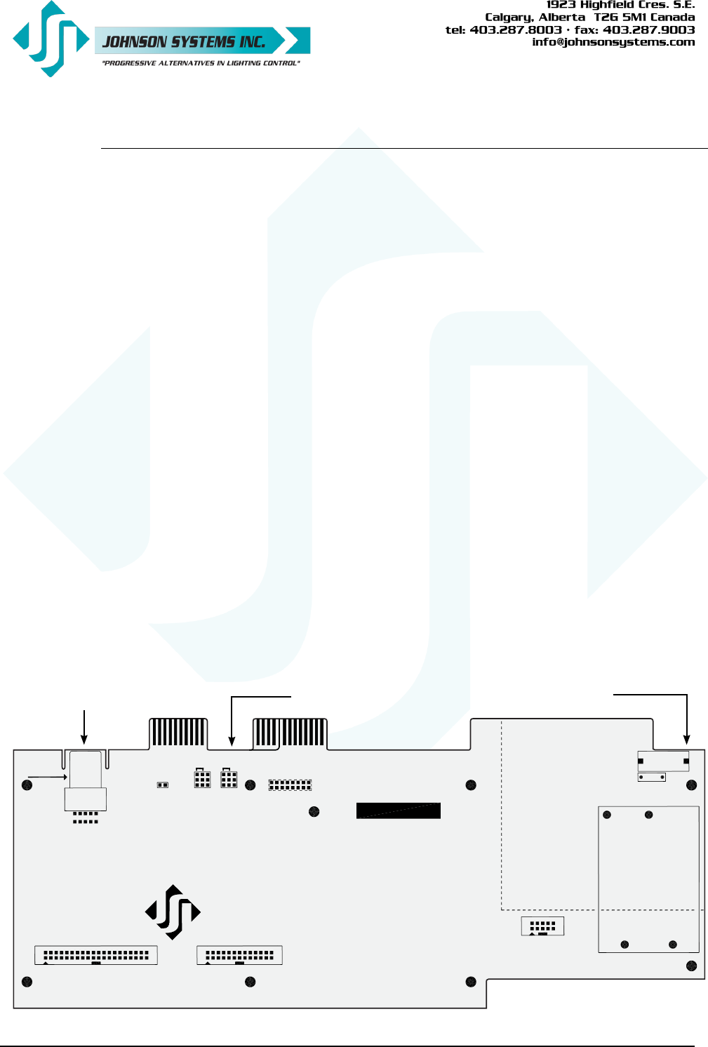
EEPROM Memory Module Enable Internal DMX-B Input Jumpers Fan Fuse
DPC-24/12 Circuit Board
The DPC-24/12 circuit board is the central electronic control system (a.k.a. brain) for DPC-12 and
DPC-24 retrot control modules. The edge connectors (EDGE1, EDGE2, EDGE3 and EDGE5 (for
DPC-24 only)) located on the upper edge of the DPC-24/12 circuit board connects with the OEM
connectors inside the CD80 dimmer pack.
There are three (3) items of interest located on the DPC-24/12 circuit board:
• Located on the upper left-hand side of the board, there is a removable EEPROM memory
module. The EEPROM memory module slides into the PORT1 connector located on
the upper left-hand side of the board. The EEPROM memory module is used to backup
important conguration settings and may be removed for safe storage. The EEPROM
memory module can also be used for rmware updates. Refer to menu items “EEPROM”,
“FW-LOAD”, “RESTORE” and “BACKUP” on page 19, 20 and 21 for further details.
• Located on the upper-central left-hand side of the board, there are two sets of jumpers. If
the DMX input is connected internally, on a terminal block mounted inside the CD80 dimmer
pack, the jumpers will need to be moved on the DPC-24/12 circuit board to enable the
DMX-B input. To enable the internal DMX through the EDGE2 connector on the DPC-24/12
circuit board, move the three (3) jumpers on JP2 to the left-hand side position. To enable the
internal DMX through the EDGE3 connector on the DPC-24/12 circuit board, move the three
(3) jumpers on JP3 to the left-hand side position.
• Located on the upper right-hand side of the board, there is a fan fuse. The fuse is required
for safety and protects the fan control circuitry on the DPC-24/12 circuit board. If the fuse
is blown (open), the “FAN” LED illuminates. A blown (open) fuse suggests the fan may
be defective and needs to be replaced (Johnson System Inc., Part Number: CF-CD80P).
Replace the fuse with a 2A, 250V, fast-acting, GMA type fuse only!